ENGINE
3-37
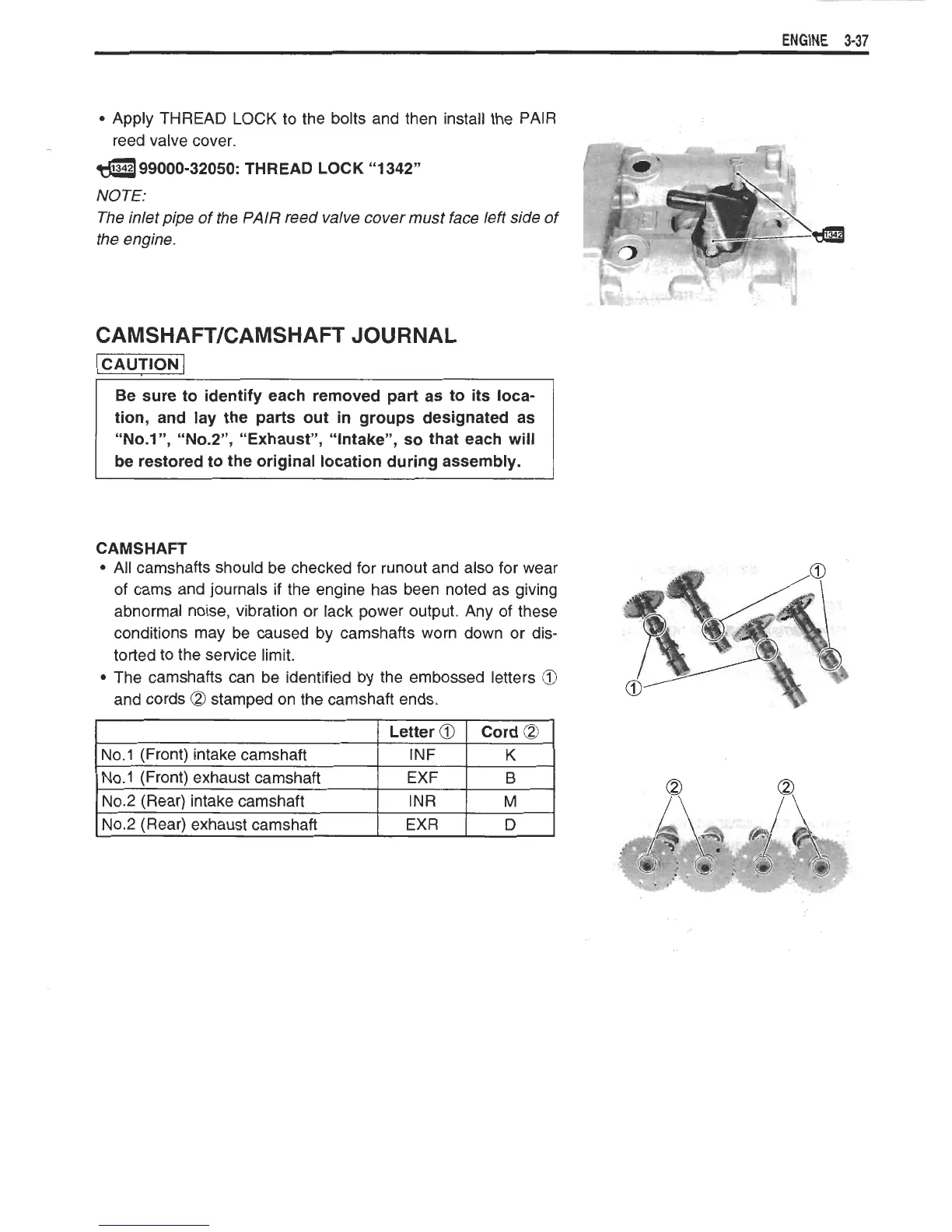
Apply THREAD
LOCK
to the bolts and then install the PAIR
reed valve cover.
p
-*
-
rr
a
99000-32050:
THREAD LOCK "1
342"
I
NOTE:
The inlet pipe of the PAlR reed valve cover must face left side of
the engine.
CAMSHAFTKAMSHAFT JOURNAL
-1
tion, and lay the parts out in groups designated as
"No.l",
NO.^",
"Exhaust", "Intake", so that each will
be restored to the original location during assembly.
CAMSHAFT
All camshafts should be checked for runout and also for wear
of cams and journals if the engine has been noted as giving
abnormal noise, vibration or lack power output. Any of these
conditions may be caused by camshafts worn down or dis-
torted to the service limit.
The camshafts can be identified by the embossed letters
@
and cords
a
stamped on the camshaft ends.
1
I
Letter
Cil
I
Cord
(23
1
1
No.1 (Front) intake camshaft
I
INF
I
K
I
I
No.1 (Front) exhaust camshaft EXF
I
6
No.2 (Rear) intake camshaft
No.2 (Rear) exhaust camshaft
INR
EXR
M
D
 Loading...