F1
SYSTEM
DIAGNOSIS
4-37
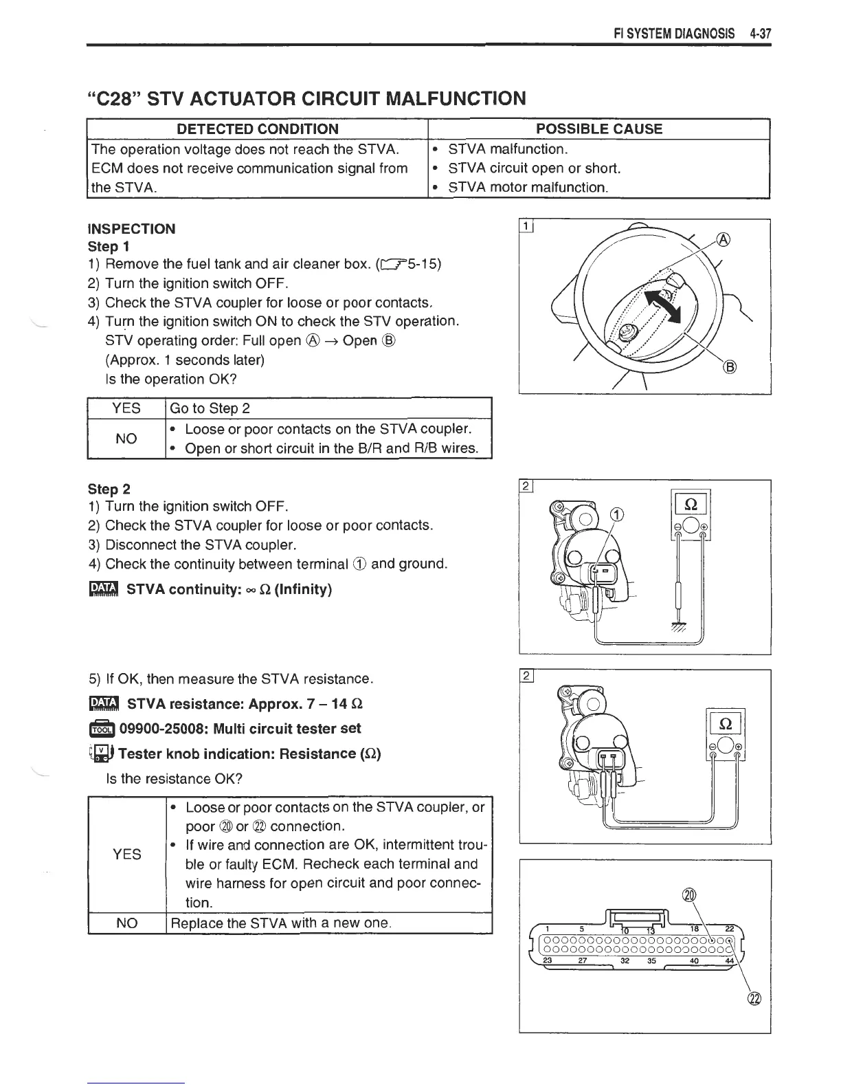
"C28" STV ACTUATOR CIRCUIT MALFUNCTION
INSPECTION
Step
1
1) Remove the fuel tank and air cleaner box. (-5-15)
2) Turn the ignition switch OFF.
3) Check the STVA coupler for loose or poor contacts.
4) Turn the ignition switch ON to check the
STV
operation.
-
S~V
operating order: Full open
@
+
Open
(Approx.
1
seconds later)
Is the operation OK?
DETECTED CONDITION
The operation voltage does not reach the STVA.
ECM does not receive communication signal from
the STVA.
1
YES )Go to Step
2
POSSIBLE CAUSE
STVA malfunction.
STVA circuit open or short.
STVA motor malfunction.
I
No
I
Loose or poor contacts on the STVA coupler.
Open or short circuit in the B/R and RIB wires.
Step
2
1) Turn the ignition switch OFF.
2) Check the STVA coupler for loose or poor contacts.
3) Disconnect the STVA coupler.
4) Check the continuity between terminal and ground.
STVA continuity:
=
R
(Infinity)
I
NO
I
Replace the STVA with a new one.
I
5) If OK, then measure the STVA resistance.
STVA resistance: Approx.
7
-
14
S2
09900-25008: Multi circuit tester set
@
Tester knob indication: Resistance
(Q)
Is the resistance OK?
YES
Loose or poor contacts on the STVA coupler, or
poor
@
or
(23
connection.
If wire and connection are OK, intermittent trou-
ble or faulty ECM. Recheck each terminal and
wire harness for open circuit and poor connec-
tion.
 Loading...