Fl
SYSTEM
DIAGNOSIS 4-33
"C21" IAT SENSOR CIRCUIT MALFUNCTION
I
DETECTED CONDITION POSSIBLE CAUSE
I
Output voltage is out of the specified range.
1
rn
IAT sensor circuit open or short.
1
0.1
V
$
Sensor voltage
c
4.6
V
IAT sensor malfunction.
ECM malfunction.
INSPECTION
Step
1
1)
Lift
and support the fuel tank.
(-5-7)
2) Turn the ignition switch OFF.
3)
Check the IAT sensor coupler for loose or poor contacts.
.-
If OK, then measure the IAT sensor voltage at the wire side
coupler.
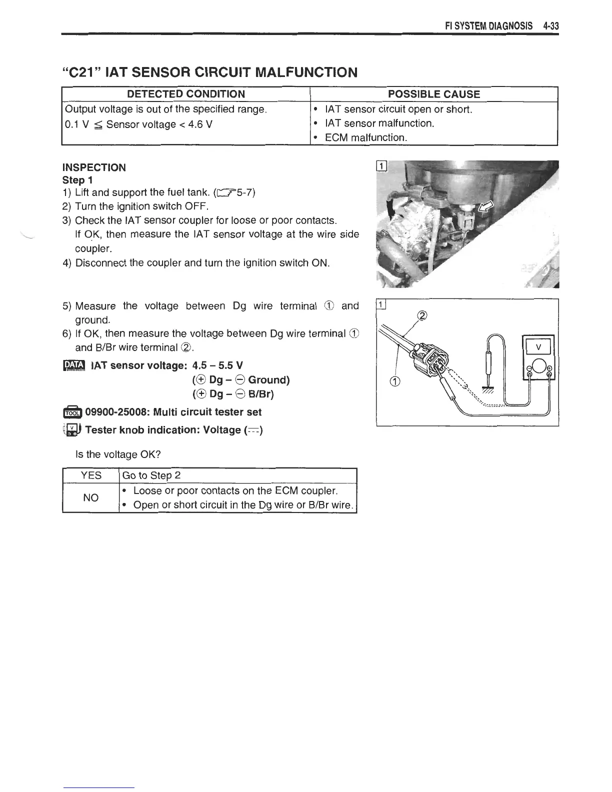
4) Disconnect the coupler and turn the ignition switch ON.
5)
Measure the voltage between Dg wire terminal
@
and
ground.
6) If OK, then measure the voltage between Dg wire terminal
@
and B/Br wire terminal
@.
IAT sensor voltage: 4.5
-
5.5 V
(@
Dg
-
@
Ground)
(@
Dg
-
@
WBr)
a
09900-25008: Multi circuit tester set
@
Tester knob indication: Voltage
(=)
Is the voltage OK?
I
YES
IGO
to Step 2
No
Loose or poor contacts on the ECM coupler.
Open or short circuit in the Dg wire or BIBr wire.