4-28
FI
SYSTEM
DIAGNOSIS
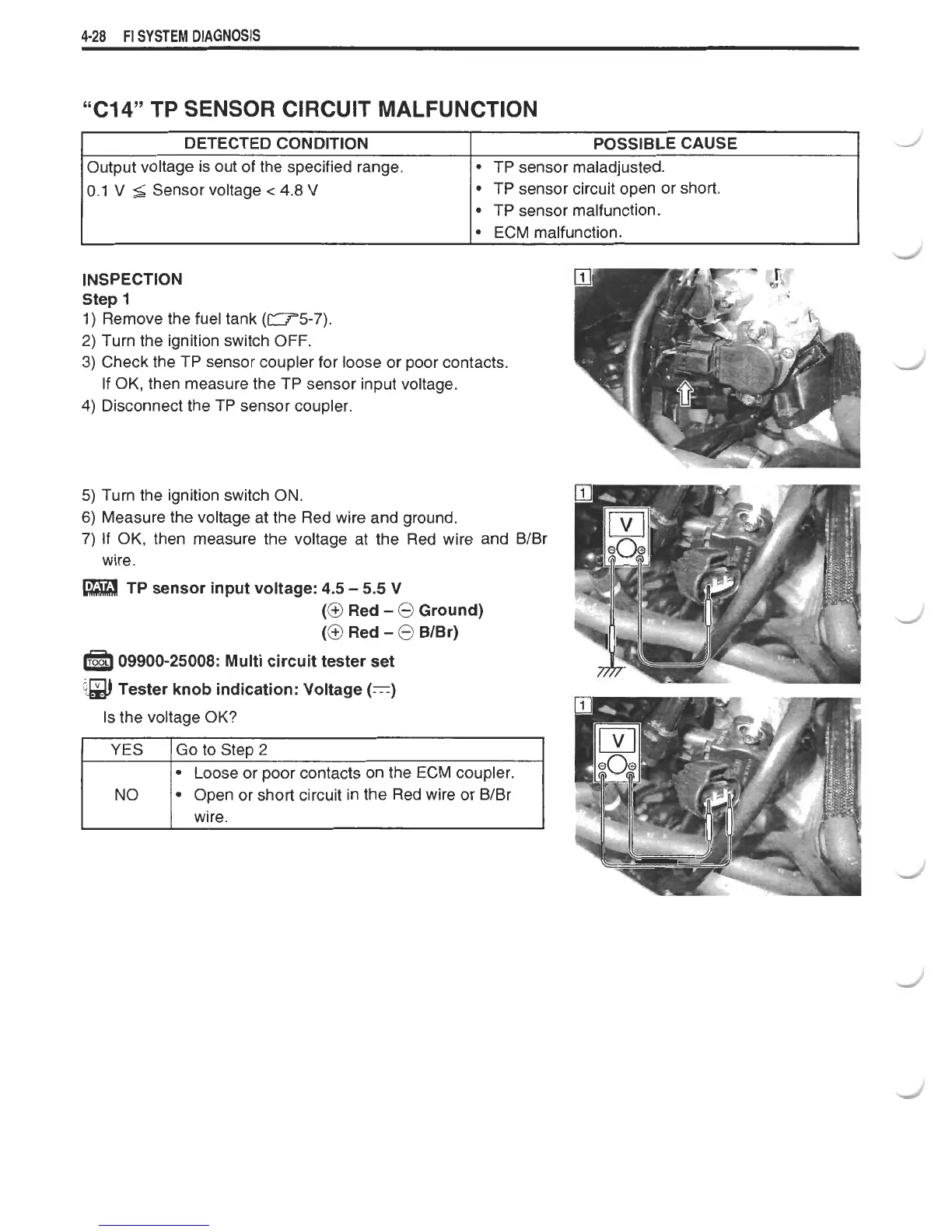
INSPECTION
Step
1
1)
Remove the fuel tank
(-5-7).
2)
Turn the ignition switch OFF.
3)
Check the TP sensor coupler for loose or poor contacts.
"C14" TP SENSOR CIRCUIT MALFUNCTION
If OK, then measure the TP sensor input voltage.
Disconnect the TP sensor coupler.
DETECTED CONDITION
Output voltage is out of the specified range.
0.1
V
5
Sensor voltage
c
4.8
V
Turn
the ignition switch ON.
Measure the voltage at the Red wire and ground.
If
OK, then measure the voltage at the Red wire and B/Br
wire.
POSSIBLE CAUSE
TP sensor maladjusted.
TP sensor circuit open or short.
TP sensor malfunction.
ECM malfunction.
TP sensor input voltage:
4.5
-
5.5
V
(@
Red
-
@
Ground)
(@
Red
-
@
BIBr)
09900-25008:
Multi circuit tester set
i)
Tester knob indication: Voltage
(=)
Is the voltage OK?
Loose or poor contacts on the ECM coupler.
Open or short circuit in the Red wire or B/Br
wire.
 Loading...