Installation
Installing in a Video System
This instrument can operate almost anywhere in the distribution system due to its high impedance, bridging, and loop-through
inputs. This section describes two types of connections and presents information on line termination. The following diagrams
are for serial digital systems, but similar connections are common for the analog composite inputs on this instrument.
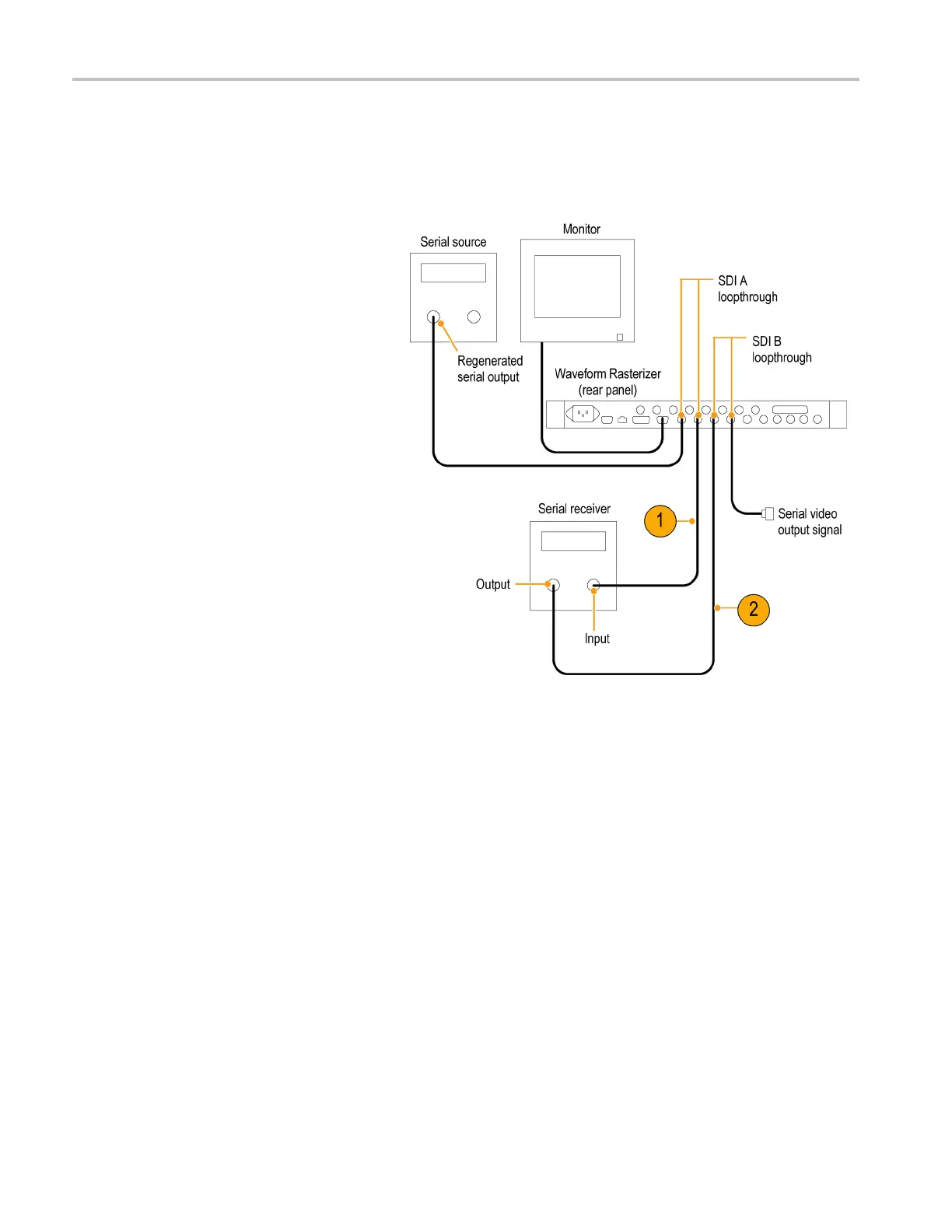
For monitoring the v ideo bit stream
of a serial receiver
1. Route the incoming serial signal
through one o
f the waveform rasterizer
loop-through inputs.
2. Connect the output of the s erial receiver
to the other loop-through input, so you
can compare
the incoming signal and
the regenerated output signal.
NOTE. See the Specifications and
Performanc
eVerification manual on the User
Documentation CD for maximum allowable
cable lengths.
8 Waveform Rasterizers Quick Start User Manual
 Loading...


