Monitoring the S
DI Physical Layer
Monitoring th
e SDI Physical Layer
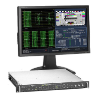
With Options EYE and PHY installed, your instrument can use an eye pattern display, eye measurements, a jitter display,
jitter detection and measurement, and an SDI status dis play to monitor and measure the SDI physical layer.
Display Types
Eye Display. This display allows you to use voltage and time measurement cursors and their readouts to monitor
amplitude and
timing measurements on an Eye waveform. You can configure y our instrument to show multiple Eye
displays, each of which is controlled by one of two jitter engines: The Jitter1 engine controls Eye displays in the top
two tiles and the J itter2 engine controls Eye displays in the bottom two tiles. The two jitter engines allow you to set
different fil
ter bandwidths in the upper and lower tiles so that you can monitor both timing and alignment jitter at the
same time. There is also a jitter thermometer in the Eye display that graphically relates the jitter measurement to alarm
limits, and there are readouts that display jitter magnitude.
Displaying the Eye waveform in a single, full-screen tile includes the measurement results and adds a histogram
display to t
he Eye waveform.
Jitter Disp
lay. On this display, you can view additional time-domain information that is useful in separating sources of
jitter, whether they are within a single circuit on a c ircuit board, or from various pieces of equipment in a system. This
includes jitter components that are synchronous or nearly synchronous to video line or video frame. These components
appear as st
ationary or near-stationary artifacts in line or field sweeps and the w ave shape of the jitter as modified by
the high-pass filter setting.
SDI Status Display. This display shows both the Jitter1 and Jitter2 t hermometers and a Cable Loss thermometer that
indicates signal loss due to cable length. With Option PHY installed, this display also shows the eye amplitude, eye
risetime,
eye falltime, eye risetime overshoot, eye falltime overshoot, and eye rise-fall delta measurement values.
Configuring Physical Layer Settings
Before you use Eye or SDI Status displays to monitor the SDI physical layer, you will need to configure the eye and physical
layer settings. These are initially set to factory defaults, w hich you can restore using the Factory front-panel button.
For more detailed information about physical layer monitoring and measurement, see the User Technical R eference on
your Customer Documentation CD.
NOTE. For instruments with Option DL or SIM, your instrument can only monitor physical layer information on one input at a
time. To make m easurements, select the input you want to monitor and then proceed with the following steps.
54 Waveform Rasterizers Quick Start User Manual

 Loading...


