CLCH-SVX07C-EN 109
Start-Up
Airflow Measuring Systems
Traq™ Dampers
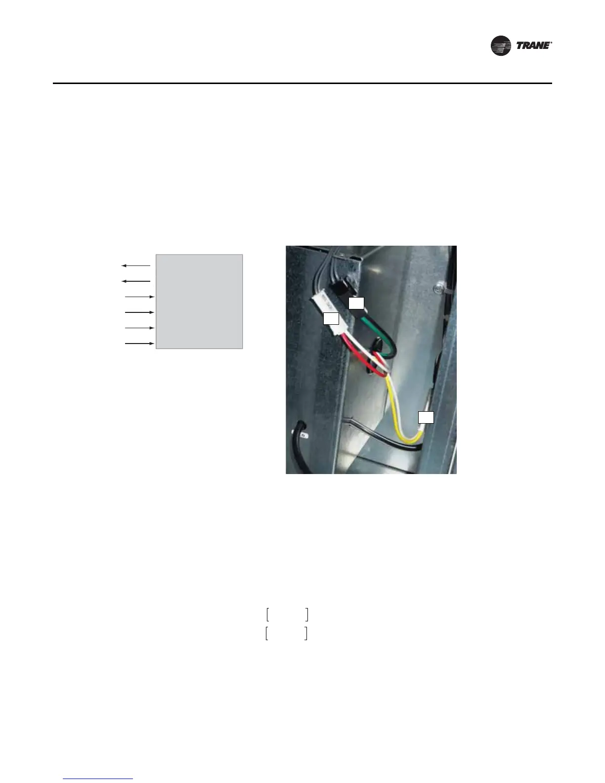
Traq dampers are low-leak dampers that modulate and measure airflow. Each Traq damper section
is supplied with a factory-mounted ventilation control module (VCM) on the interior of the mixing
box section. The VCM has an input terminal for power and an output terminal for air velocity (see
Figure 96). A direct-digital controller controls the factory-mounted and wired actuators.
VCM (Transducer) Calibration. The VCM has an auto-zero function that recalibrates the
transducer once every minute. When troubleshooting, allow for the recalibration time before
making any measurements.
Input Power. The only input the VCM needs is the 24 Vac power connected to terminals 1TB1–5
and 1TB1–6.
Output Velocity Signal. The 2 to 10 Vdc linear output signal from the VCM represents air
velocity. This voltage can be converted to represent airflow (cfm or L/s) using the formula below
and Table 27 .
Figure 96. Traq damper terminal connections
Ventilation Control Module
Velocity (2-10 Vdc)
GND
24 Vac
GND
J4 (Red)
J4 (White)
J2 (Black)
J2 (Green)
J5 (Yellow)
J5 (White)
Thermistor
J5
J4
J2
Airflow = k (cfm @ 10V)
or
Airflow = k (L/s @ 10V)
For example, if the VCM on a size 30 air handler at sea level (k=1) has a 10-volt signal, it
would represent 24,492 cfm (11,559 L/s) through the Traq damper. If the voltage were
6 volts, airflow through the Traq damper would be 12,246 cfm (5779 L/s).
volts 2–()
8
------------------------------
volts 2–()
8
------------------------------
 Loading...
