80 CLCH-SVX07C-EN
Coil Piping and Connections
Drain Pan Trapping
WARNING
No Step Surface!
Do not walk on the sheet metal drain pan. Walking on the drain pan could cause the supporting
metal to collapse. Failure of the drain pan could result in death or serious injury.
Threaded condensate drain connections are provided on only one side of the coil section. Pitch the
connection lines horizontal or downward toward an open drain. Trane recommends installing a
plug to facilitate cleaning of the trap. The drain connection sizes are:
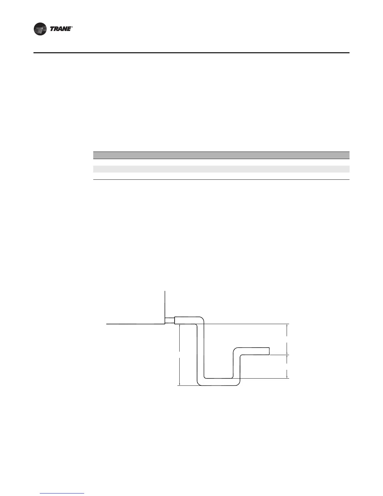
Figure 71 illustrates the proper trapping, piping, and operation of the trap. Use the formula under
the figure to determine the correct minimum depth for the condensate trap. If a section has a drain
pan for cleaning purposes only, it does not need a trap; however, a cap or shutoff valve should be
installed on the drain connection. Only sections handling condensate, such as a cooling coil section
or moisture eliminator section, require a trap.
NOTICE:
Water Damage!
When more than one section has a drain pain, trap each section individually. Connecting all
drains to a common line with only one trap could result in condensate retention and possible
water damage to the air handler or adjoining space.
Unit size NPT (national pipe thread) external connection
3-30 1-inch
35-57 1 1/4 inch
66-120 1 1/2 inch
Figure 71. Drain pan trapping for negative and positive pressure applications
H
J
L
Drain pan trapping for section
under negative pressure
L = H + J + pipe diameter where:
H = 1 inch for each inch of negative
pressure plus 1 inch
J = 1/2 H
Drain pan trapping for section
under positive pressure
L = H + J + pipe diameter where:
H = 1/2 inch (minimum)
J = 1/2 inch plus the unit positive static
pressure at coil discharge
(loaded filters)
 Loading...
