76 CLCH-SVX07C-EN
Component Installation Requirements
Traq Damper Connections
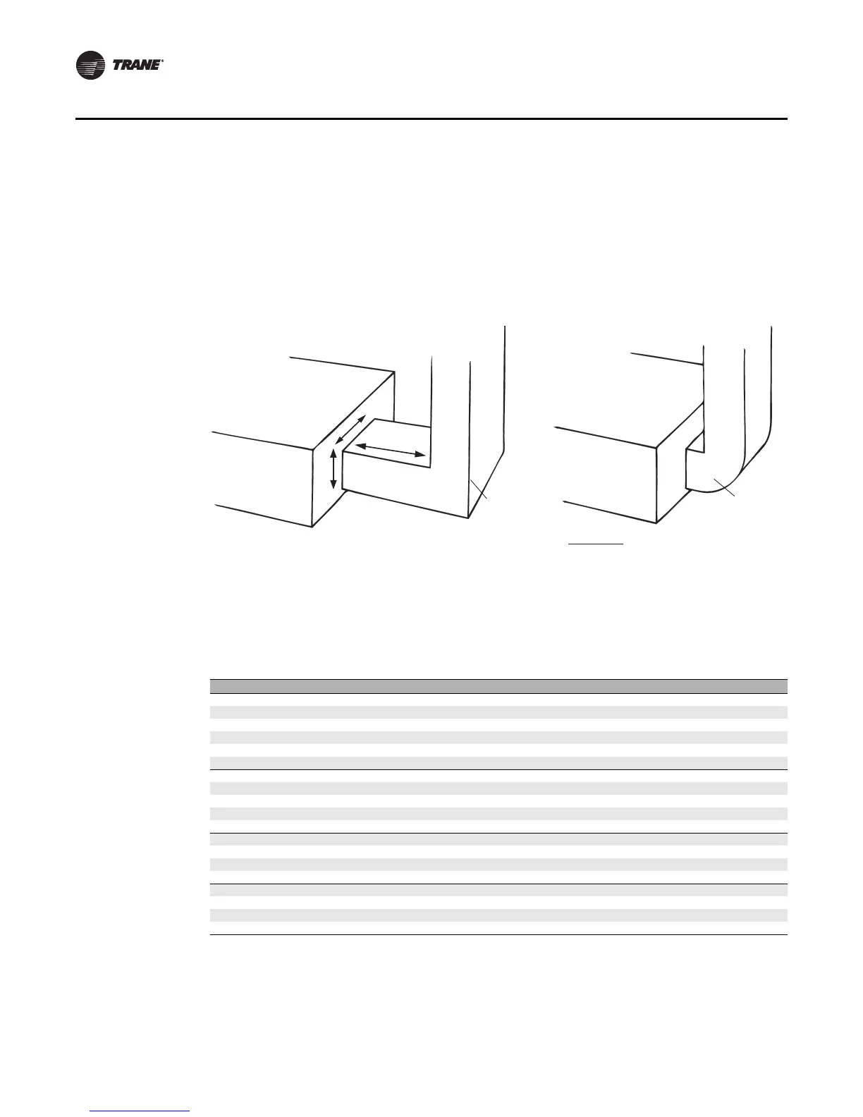
Size the duct connections to attach to the specified portion on the face of the mixing box that the
duct connection completely covers all of the Traq damper.
For a mitered corner, provide one hydraulic duct diameter between the entering face of the Traq
dampers and the duct turn. For a radius elbow, or sweep, place the elbow directly against the face
of the Traq dampers (see Figure 65).
External Face-and-Bypass Connections
The external face-and-bypass damper sections will require a field-fabricated duct to direct the
bypass air into the appropriate section. Duct sizing recommendations are listed in Table 23.
Figure 65. Traq damper duct connections
Traq damper
mixing box
Inlet duct
Traq damper
mixing box
Radius elbow
(sweep)
Mitered
corner
W
d
H
d = 1 hydraulic duct diameter = 2 x W x H
W + H
Table 23. Recommended bypass duct sizes (inches)
Unit size H W L
3 162014
4 18 33 16
6 183316
8 18 39 16
10 18 50 16
12 22 55 20
14 22 61 20
17 22 61 20
21 28 69 26
25 28 69 26
30 28 82 26
35 45 80 36
40 45 93 36
50 45 106 36
57 47 106 40
66 48 121 40
80 56 121 48
100 56 135 48
120 56 162 48
 Loading...
