•Transversejointsillustrated
can be applied as top and
bottom joints with Drive Slip
- side joints in duct heights
up to 20 inches (508mm)
See Fig. 13.
Round and Oval Duct Breakaway Connections
RoundorflatovalductsconnectedtoTypeRorOdamper
collars shall be attached with #10 (19mm) sheet metal
screws as follows:
•Ductsto22in.(558mm)wide(ordia.)andsmaller
shall have three screws.
•Ductslargerthan22in.(558mm)wide(ordia.)upto
and including 36 in. (914mm) wide (or dia.) shall have
five screws.
NOTE: All breakaway connections described may have duct
sealant applied, PA2084T duct sealant adhesive
manufactured by Precision, DP1010 water base duct
sealant manufactured by Design Polymetrics, Grey Pookie
orDuctmatePROseal
®
in accordance with SMACNA
recommendations.
Manufactured Flanged System Breakaway
Connections
Flanged connection systems manufactured by Ductmate,
Ward, and Nexus are approved as breakaway connections
when installed as illustrated (Fig. 15).
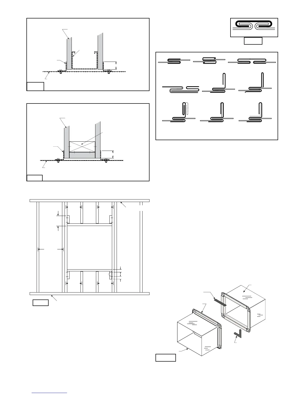
Wooden Stud Construction
In wood stud construction,
gypsum wallboard must cover
all wood stud surfaces.
Gypsum Wallboard
Stud or Runner
Retaining
Angle
1 in. Min.
Damper
Sleeve
In metal stud construction,
exposed steel surfaces need
not be covered with gypsum
wallboard.
Gypsum Wallboar d
Stud or Runner
Retaining
Angle
1 in. Min.
Damper
Sleeve
Fig. 11
12 in.
24 in. o.c.
Maximum
Floor Runner
Ceiling Runner
24 in. o.c.
Maximum
(metal studs)
24 in. o.c.
Maximum
(metal studs)
16 in. o.c.
Maximum
(wood studs)
16 in. o.c.
Maximum
(wood studs)
2 in. (51mm)
2 in. (51mm)
2 Panhead
Screws
Fig. 12
9. DUCT-SLEEVE CONNECTIONS
Traditional Breakaway Style Transverse Joints
Transverse joints illustrated at right have always been
approved as breakaway connections. SMACNA testing
has also approved the following variations as breakaway
connections.
•Thebreakawayconnectionsshown(Fig. 14) can
be applied with maximum of two #10 (19mm)
sheet metal screws on each side and on the
bottom located in the center of the slip pocket and
penetrating both sides of the slip pocket.
Fig. 13
Plain “S” Slip Hemmed “S” Slip Double “S” Slip
Inside Slip Joint Standing “S” Standing “S” (Alt.)
Standing “S” (Alt.) Standing “S” Standing “S”
(Bar Reinforced) (Angle Reinforced)
Fig. 14
Fire Damper Sleeve
Neoprene gasket
between all angles
Flanged system angles
(Attach per
manufacturer's
instructions)
Duct
Do not bolt corners
6 in. long
1
/16 in. max.
thickness plastic cleats;
12 in. c-c (min. 1 per side)
Fig. 15
7
Metal Stud Construction
Wooden Stud Construction
In wood stud construction,
gypsum wallboard must cover
all wood stud surfaces.
Gypsum Wallboard
Stud or Runner
Retaining
Angle
1 in. Min.
Damper
Sleeve
In metal stud construction,
exposed steel surfaces need
not be covered with gypsum
wallboard.
Gypsum Wallboar d
Stud or Runner
Retaining
Angle
1 in. Min.
Damper
Sleeve
Fig. 10
 Loading...
