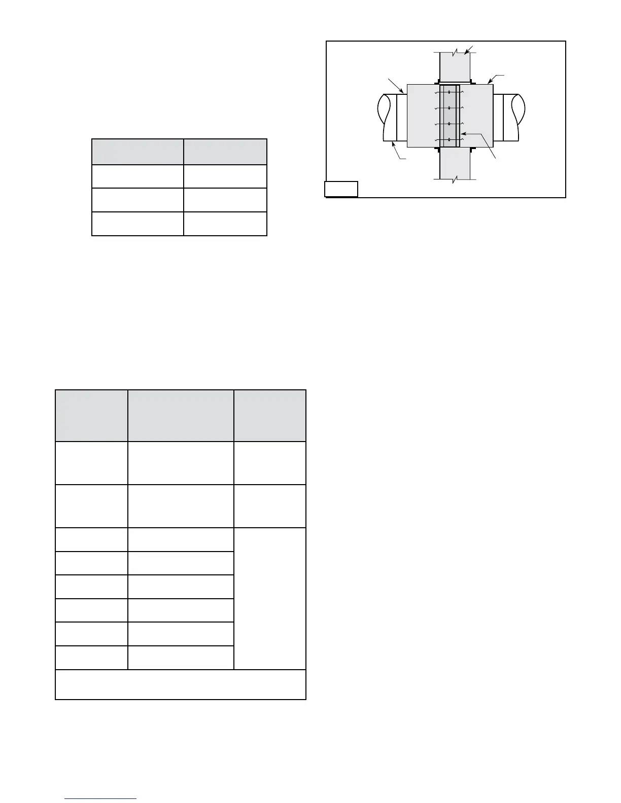
3. DUCT TO SLEEVE CONNECTIONS
Dampers are supplied with sleeves and actuators from
the factory and can be installed without the need for
additional field installed sleeves.
Gauge of factory furnished sleeve determines the
type of duct to sleeve connections required (see table
below). Any duct connection other than the breakaway
connections described on page 7 are considered rigid.
Factoryfurnishedductcollars,typeRandO,arealso
considered breakaway (see Fig. 2).
Wall or Floor
Sleeve
Duct
Damper
Type B
Wall or Floo
r
Sleeve
Duct
Damper
Type C, R
Type R and O
factory furnished
duct collars qualify
as breakaway
connections.
Fig. 2
Wall Thickness
Dimension (T
W
)
Sleeve Length
Dimension (L)
4 - 6 in.
(102mm - 152mm)
16 in.
(406mm)
7 - 10 in.
(178mm - 254mm)
21 in.
(533mm)
11 - 13 in.
(279mm - 330mm)
24 in.
(610mm)
Sleeve Gauge Duct Dimension
Type of Duct
to Sleeve
Connection
Permitted
14 ga. (0.075 in.)
- 10 ga. (0.138
in.)
[2mm - 3.5mm]
All duct sizes
Rigid or
Breakaway
16 ga. (0.060 in.)
[1.5mm]
36 in. (914mm) max. width
24 in. (610mm) max.
height
24 in. (610mm) diameter
Rigid or
Breakaway
16 ga. (0.060 in.)
[1.5mm]
All duct sizes
Breakaway only
18 ga. (0.048 in.)
[1.2mm]
85 in. (2159mm) wide and
over
20 ga. (0.036 in.)
[0.9mm]
55 in. - 84 in. wide
(1397mm - 2134mm)
22 ga. (.030 in.)
[0.76mm]
31 in. - 54 in. wide
(787mm - 1372mm)
24 ga. (0.024)
[0.6mm]
13 in. - 30 in. wide
(330mm - 762mm)
26 ga. (0.018 in.)
[0.46mm]
12 in. wide and under
(305mm)
See page 7 for additional information on breakaway sleeve connections.
Sleeve thickness must not be less than the gauge of the connecting duct.
UL Standard 555 requires all ducts to terminate at fire damper sleeves.
4. SECURING THE DAMPER/SLEEVE ASSEMBLY
TO WALL AND FLOOR OPENINGS (for single side
retaining angle instructions, see supplements)
Damper/sleeve assemblies must be installed in wall and
floor openings using retaining angles on at least one
side of the wall or floor as described below:
•Retaining angles for 1½ hour rated dampers with a
width and height 48 in. (1219mm) or less must be a
minimum of 20 ga. (1mm). Retaining angles for all
3 hour rated dampers and all dampers with a width
or height greater than 48 in. (1219mm) must be a
minimum of 16 gauge (1.5mm). The leg of the retaining
angle on the damper sleeve shall be a minimum of
1¼ in. (32mm). The leg of the retaining angle on the
wall/floor shall be long enough to cover the annular
space and overlap the wall/floor by a minimum of 1 in.
(25mm).
•Retaininganglesmustbeattachedtothedamper
using one or more of the following methods of
attachment (refer to label on outside of sleeve for ‘No
Screw’ area):
•Tackorspotwelds
•#10(
3
/4 in. [19mm] max.) sheet metal screws
•
1
/4 in. (6mm) bolts and nuts
•
3
/16 in. (5mm) steel pop rivets
A minimum of two connections per side, top, and
bottom,12in.(305mm)O.C.maximumforopeningsof
48 in. W x 36 in. H (1219mm x 914mm) and less, and 6
in.(152mm)O.C.foropenings80in.Wx50in.H
(2032mm x 1270mm), 50 in. W x 72 in. H (1270mm x
1829mm), and 40 in. W x 72 in. H (1016mm x 1829mm)
or less. The angles must be attached to all 4 sides of the
sleeve. Ensure that attachment device does not interfere
with the operation of the damper and the free movement
of the damper blades. The angles need not be attached
to each other at the corners. Do not secure the retaining
angle to the fire separation (see Fig. 3).
•Retaininganglesshouldnotbefastenedtothewall/
floor material. The angles should only sandwich the
wall/floor and allow for damper expansion during
periods of intense heat.
4
IMPORTANT SAFETY DANGER! : To avoid causing
death or serious bodily harm to building occupants, do
not penetrate the ‘No Screw’ area designated on the
damper sleeve or the damper may not close properly.
The sleeve may extend a maximum of 16 in. (406mm)
beyond the wall or floor on the actuator side of the
damper and a maximum of 6 in. on the opposite side.
Recommended standard sleeve lengths for various wall
thicknesses are:
 Loading...
