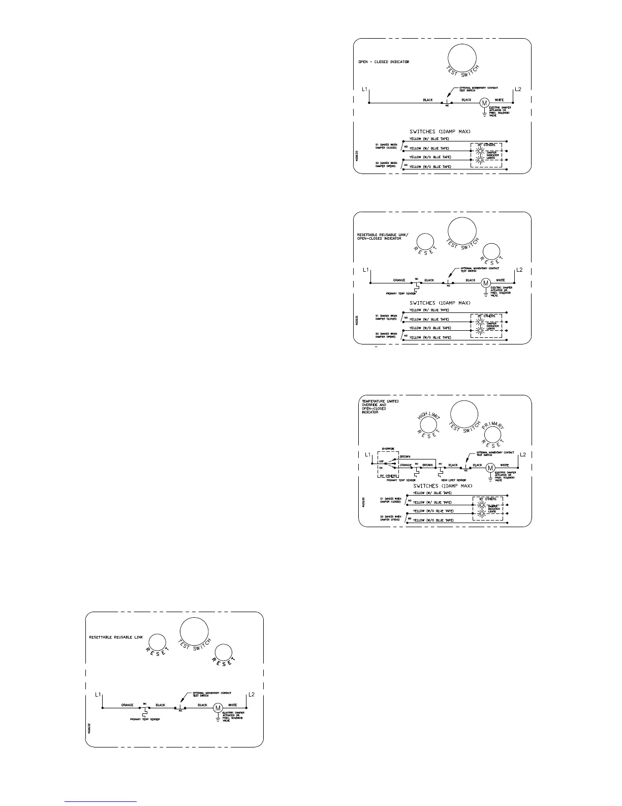
OCI -TheOCI(openorclosedindicator)option
contains a single pole, double throw switch used
to indicate the damper blade position. The switch
provides a positive open or closed signal when used in
conjunction with remote indicator lights. Refer to Fig. 7
& 8forwiringoftheOCIoption.
TOR -TheTOR(temperatureoverridedevice)option
incorporates two thermostats with fixed settings (usually
165°F [74°C] and 350°F [177°C]). The primary sensor
(the sensor with the lower temperature setting) can be
bypassed by an external electrical signal allowing the
damper to reopen until the temperature reaches the
setting of the secondary sensor (the sensor with the
higher temperature setting).
See Fig. 8.
When the temperature of the secondary sensor is
exceeded the damper closes and remains closed
thereafter.
TheTORassemblyalsocontainsasinglepole,double
throw switch used to indicate damper blade position.
The switch provides a positive open or closed signal
when used in conjunction with remote indicator lights.
SeeFig.8forwiringoftheTORthermostatsand
indicator switches.
IfeithertheTORortheRRLisorderedwithapneumatic
actuator, an EP switch is required with an appropriate
electric power circuit to allow the electric thermostat to
control the pneumatic actuator.
PRV - The PRV (pneumatic relief valve) option is heat
responsive device used with pneumatic actuators. This
can be used in place of EP switch where a RRL is used.
The PRV activates when temperature in excess of the
temperature of the fusible link are detected. When the
fusible link melts, air from the actuator is exhausted to
close the dampers. Pneumatic actuators are to be piped
per local code.
RATINGS (Fig. 6, 7, 8 & 9)
Integral Switch Type: Single Pole, double throw
Electrical Capacity: 10 Amps,
1
/3 hp, 120 or 240 Vac
1
/2 Amp, 125 Vdc;
1
/4 Amp 250 Vdc
5 Amps, 120 Vac “L” ( lamp load)
1.0 Amps, 24 Vac
1.5 Amps, 24 Vdc
Temperature Limit: 165° F (standard primary sensor)
212° F (optional primary sensor)
250° F (secondary sensor )*
350º F (secondary sensor)*
* based on actuator temperature rating
Fig. 6 RRL Wiring
Fig. 7 OCI Wiring
Fig. 9 TOR Wiring
8. Recommended Preparation of Openings in Wood
and Metal Stud Walls
•Framewallopeningsasshownbelow
(see Fig. 10 & 11).
•Doubleverticalstudsarenotrequiredforopenings
36 in. x 36 in. (914mm x 914mm) or smaller.
•Gypsumwallboardmustbefastened12in.(305mm)
on center to all stud and runner flanges surrounding
opening (see Fig. 12).
•Allconstructionandfastenersmustmeetthe
requirements of the appropriate wall design (See UL
Fire Resistance Directory) and/or local codes.
6
Fig. 8 RRL/OCI Wiring
 Loading...
