6
Section 3. Unit Preparation
3.1 Prepare The Unit For Installation
STEP 1 - Check for damage and report promptly to
the carrier any damage found to the unit.
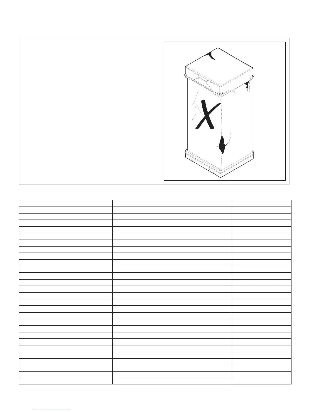
Note: If the unit must be transported in a horizontal
position, it must be laid on its back (marked “REAR”
on carton).
Note: After the unit is removed from the carton,
depress the Schrader valve to verify coil is pressur-
ized.
3.2 Unit Accessories
Accessory Number Description Fits Cabinet Size
BAYEAAC05BK1A Electric Heater, 5kW, Breaker, 24V Control, 1 Ph A to C
BAYEAAC05LG1A Electric Heater, 5kW, Lugs, 24V Control, 1 Ph A to C
BAYEAAC08BK1A Electric Heater, 8kW, Breaker, 24V Control, 1 Ph A to C
BAYEAAC08LG1A Electric Heater, 8kW, Lugs, 24V Control, 1 Ph A to C
BAYEAAC10BK1A Electric Heater, 10kW, Breaker, 24V Control, 1 Ph A to C
BAYEAAC10LG1A Electric Heater, 10kW, Lugs, 24V Control, 1 Ph A to C
BAYEAAC10LG3A Electric Heater, 10kW, Lugs, 24V Control, 3 Ph A to C
BAYEABC15BK1A Electric Heater, 15kW, Breaker, 24V Control, 1 Ph B to C
BAYEABC15LG3A Electric Heater, 15kW, Lugs, 24V Control, 3 Ph B to C
BAYEABC20BK1A Electric Heater, 20kW, Breaker, 24V Control, 1 Ph C
BAYEACC25BK1A Electric Heater, 25kW, Breaker, 24V Control, 1 Ph C
BAYSUPFLGAA Supply Duct Flange A A
BAYSUPFLGBA Supply Duct Flange B B
BAYSUPFLGCA Supply Duct Flange C C
BAYRETFLGAA Return Duct Flange A A
BAYRETFLGB Return Duct Flange B B
BAYRETFLGCA Return Duct Flange C C
TASB175SB Plenum Stand with integrated sound baffle A A
TASB215SB Plenum Stand with integrated sound baffle B B
TASB235SB Plenum Stand with integrated sound baffle C C
BAYSRKIT100A Side Return Kit A to C
BAYICSKIT01A Internal Condensate Switch Kit A to C
BAYHHKIT001A Horizontal Hanger Kit A to C
BAYUVCLK001A UVC Lights A to C
BAYLVKIT100A Low Voltage Conduit Entry Kit A to C
MITISRKIT1620 Side Return Kit with Filter A to C
BAYSPEKT200A Single Power Entry Kit A to C
Table 3.1
 Loading...
