Home
Trane
Air Handlers
AM4A0A30S21SA Series
Trane AM4A0A30S21SA Series User Manual
4
of 1
of 1 rating
251 pages
Give review
Manual
Specs
To Next Page
To Next Page
To Previous Page
To Previous Page
Loading...
37
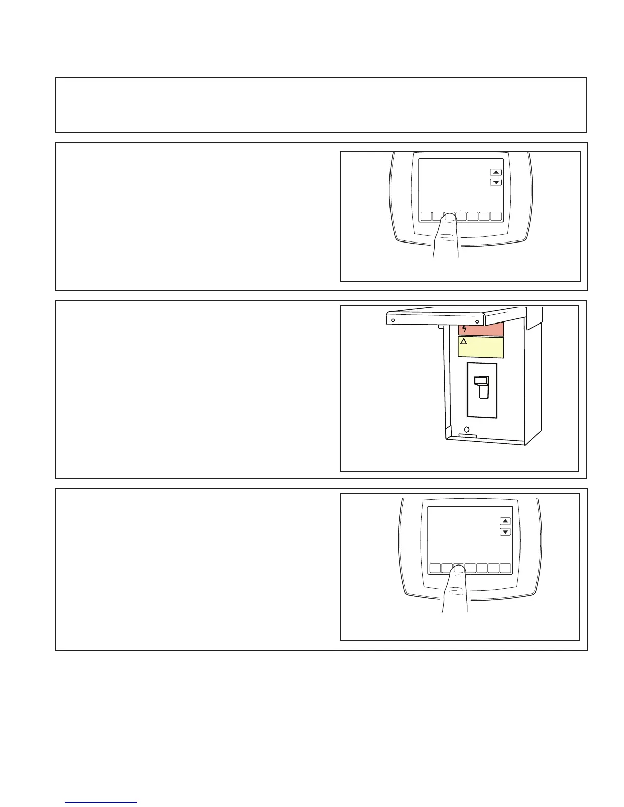
Section 17.
Star
t Up
STEP 2
- Set the system thermostat to OFF
.
STEP 3
-
T
ur
n on electrical power disconnect(s) to
apply power to the indoor and outdoor units
.
STEP 4
- Set the system thermostat to ON.
OFF
D
O
N
E
CANCEL
ON
OFF
ON
D
O
N
E
CANCEL
STEP 1
- Make sure all panels are securely in place
and that all wiring has been proper
ly dressed and
secured.
17.1 System Start Up
172
174
Table of Contents
Table of Contents
9
Default Chapter
7
Section 1. Safety Information
7
Introduction
8
Overview of Manual
8
Nameplate
8
Section 2. Unit Design
8
Table of Contents
9
General Information
13
Operating Environment
13
Unit Description
13
Factory-Mounted Controls
13
Pre-Packaged Solutions for Controls
14
Wiring
14
Pre-Installation Requirements
15
Receiving Checklist
15
Assembly Hardware
16
Resolving Shipping Damage
16
Storage Recommendations
16
Section 5. Place Unit at Location
16
General Storage
17
Long-Term Storage
17
Outdoor Storage Considerations
17
Preparing the Unit Site
17
Section 6. Unit Location Considerations
17
Roof Curb Installation Checklist
18
Unit Dimensions and Weights
20
Service Clearances
20
Fans/Motors
27
Starter/Vfd Weights
27
Motor Weights
27
Installation - Mechanical
28
Lifting and Rigging
28
Remove Shipping Tie-Downs
28
General Lifting Considerations
29
Lifting Inlet and Exhaust Hoods and External Pipe Cabinet (Chase)
31
Forklifting Considerations for Indoor Units Size 3-30
32
Unit Placement and Assembly
32
Unit Placement
33
Unit Assembly
34
Ceiling Suspension for Indoor Air Handlers Sizes 3-57
34
Section-To-Section Assembly
36
Pipe Cabinet Installation
44
Outdoor Unit Weather Hood(S)
46
Indoor Dual-Path Split Dehumidification Unit (Sdu)/Winterizer Assembly
47
Horizontal Sdu/Winterizer Indoor Air Handler Assembly
48
Vertical Sdu/Winterizer Indoor Air Handler Assembly
50
External Raceway Assembly
52
Component Installation Requirements
53
Diffuser Sections
53
Filter Sections
53
Filter Installation
54
Filter Placement
55
Fan Sections
65
Fan Isolation
65
Adjusting the Isolators
65
Seismic Isolation Requirements
66
Anchor Requirements
66
Damper Sections
68
Damper Torque Requirements
68
Opposed-Blade and Parallel-Blade Dampers
75
Duct Connections
75
Fan Discharge Connections
75
Damper Connections
76
Bottom Opening Duct Installation
77
Discharge Plenum Connections
79
Bellmouth Discharge Connections
79
Traq Damper Connections
80
External Face-And-Bypass Connections
80
Other Connections
82
Coil Piping and Connections
83
General Recommendations
83
Drain Pan Trapping
84
Steam Coil Piping
85
Water Coil Piping
87
Refrigerant Coil Piping
89
Liquid Lines
90
Suction Lines
91
Examples of Field-Installed Evaporator Piping
93
Installation - Electrical
99
Quick Connects
103
Controls Interface
104
Connecting the Operator Display
104
Setting up the Operator Display
104
Calibrating the Operator Display
105
Adjusting Brightness and Contrast
105
External Communications Port
105
Start-Up
106
Pre-Startup Checklist
106
General Checks
106
Fan-Related Checks
107
Coil-Related Checks
107
Motor-Related Checks
108
Unit Operation
108
Calculate Motor Voltage Imbalance
109
Tension the Fan Belt
110
Determine Fan Speed
111
Align Fan and Motor Sheaves
112
Check Multiple Belts
112
Airflow Measuring Systems
113
Traq™ Dampers
113
Fan Inlet Airflow Measuring System
118
Wiring
118
Transmitter Calibration
118
Constant Factor K
119
External Insulating Requirements
121
Troubleshooting
122
Routine Maintenance
124
Maintenance Checklist
124
Air Filters
125
Throwaway Filters
125
Permanent Filters
125
Cartridge or Bag Filters
125
Drain Pans
125
Fans
126
Inspecting and Cleaning Fans
126
Bearing Set Screw Alignment
127
Fan Bearing Lubrication
127
Motor Bearing Lubrication
128
Fan Motor Inspection
128
Coils
128
Steam and Water Coils
128
Refrigerant Coils
129
Coil Winterization
130
Moisture Purge Cycle
131
Cleaning Non-Porous Surfaces
131
Cleaning Porous Surfaces
132
Ultraviolet (UV) Light Maintenance
132
Cleaning the Bulbs
133
Replacing the Bulbs
133
Disposal of Bulbs
134
Table of Contents
138
Section 3. Unit Preparation
142
Section 4. Optional Cabinet Disassembly
143
Section 7. Setting the Unit - Vertical Installation
154
Section 8. Setting the Unit - Horizontal Installation
156
Section 9. Connecting the Duct Work
157
Section 10. Refrigerant Line
158
Section 11. Refrigerant Line Brazing
159
Section 12. Condensate Drain Piping
162
Section 13. Electrical - Low Voltage
164
Section 14. Electrical - High Voltage
169
Section 15. Filters
171
Section 16. Unit Outline Drawing
172
Section 17. Start up
173
Section 18. Sequence of Operation
174
Section 19. Checkout Procedures
175
Installation/Maintenance
222
Installation
223
Clearances Required Between Fire Damper Sleeves And Wall/Floor Openings
223
2. SLEEVE Length and Wall Thickness
223
3. DUCT to SLEEVE Connections
224
Securing The Damper/Sleeve Assembly To Wall And Floor Openings
224
5. Actuator Connections
225
Installing Multiple Damper Section Assemblies
225
Recommended Preparation Of Openings In Wood And Metal Stud Walls
226
Breakaway Connections
227
Maintenance
229
4
Based on 1 rating
Ask a question
Give review
Questions and Answers:
Need help?
Do you have a question about the Trane AM4A0A30S21SA Series and is the answer not in the manual?
Ask a question
Trane AM4A0A30S21SA Series Specifications
General
Brand
Trane
Model
AM4A0A30S21SA Series
Category
Air Handlers
Language
English
Related product manuals
Trane AM4A0A36S31SA Series
251 pages
Trane AM7A0C60H51SA Series
28 pages
Hyperion AM8A0A24V21CA Series
36 pages
American Standard 4MXD8509A10N0
28 pages
Trane A4AH4 Series
32 pages
Trane A4AH4E24A1B60A
32 pages
Trane A4AH5V36A1C30A
32 pages
Trane AAM7A0C36H31SA
28 pages
Trane A4AH4E36A1C30A
32 pages
Trane AAM7A0B30H21SA
28 pages
Trane AAM7A0C42H31SA
28 pages
Trane A4AH4E30A1B30A
32 pages
 Loading...
