62 CLCH-SVX07C-EN
Component Installation Requirements
Seismic Isolation Requirements
Air handling equipment manufactured by Trane is capable of structurally and operationally
withstanding the seismic response criteria as required by the International Building Codes (IBC)
2000,2003, 2006, 2009. Trane has third-party certification for IBC compliance for seismic
applications for unit sizes 3-30. Certification for larger sizes is in process.
Note: If seismic isolation has been specified, the following requirements must be adhered to for
installation. Failure to follow these instruction would void the warranty.
Anchor Requirements
Single Level Design Break
Size 3-30 - Grade to Roof Mounted (0<=Sds<=1.85) Non-Isolated
4000 psi concrete
• 3/8-inch diameter Hilti Kwik Bolt TZ carbon steel concrete anchors attached to unit base rails.
• Quantity (2) anchors at AHU ends, (quantity (1) at each side)
• Quantity (2) anchors at AHU unit splits, quantity (1) at each side, staggered.
• 2-inch minimum anchor embedment
• 4-3/8-inch minimum distance to the nearest edge
• 4-inch minimum concrete slab thickness
Steel dunnage/steel curb
3/8-inch diameter ASTM A325 or SAE grade 5 bolts attached to unit base located as noted above
or 1-inch long 3/16-inch welds at unit base located as noted above.
Stacked Design Break
Size 3-30 – Grade to Roof Mounted (0<=Sds<=1.85) Non-Isolated
4000 psi concrete
• 1/2-inch diameter Hilti Kwik Bolt TZ carbon steel concrete anchors attached to unit base rails.
• Quantity (2) anchors at AHU ends (quantity (1) at each side).
• Quantity (2) anchors at AHU unit splits, (quantity (1) at each side, staggered).
• 3 1/4-inch minimum anchor embedment
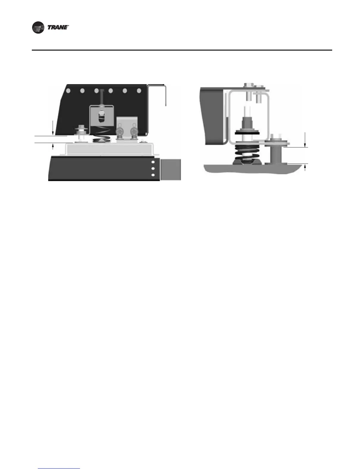
Figure 53. Isolator tie-down removal for unit sizes 66-120 Figure 54. Belt-drive plenum fan tie down
Required
clearance
 Loading...
