CLCH-SVX07C-EN 61
Component Installation Requirements
Fan Sections
The fan section can be configured as either draw-thru or blow-thru. Review the submittals and unit
tagging information prior to assembly to determine placement.
Fan Isolation
The fan-and-motor assembly is internally isolated. The fan and motor bases are bolted to a
minimum of four spring isolators. The isolators are secured to the fan section support base.
Shipping tie-down bolts are bolted adjacent to the isolators between the fan isolation base and the
isolator support frame. The shipping tie-downs secure the isolation base to the support assembly
to prevent any damage to the fan section during shipment.
Note: Remove the tie-downs only if the factory-provided isolation is to be used.
Adjusting the Isolators
Note: For additional information regarding the safe discharge of capacitors, see
PROD-SVB06A-EN.
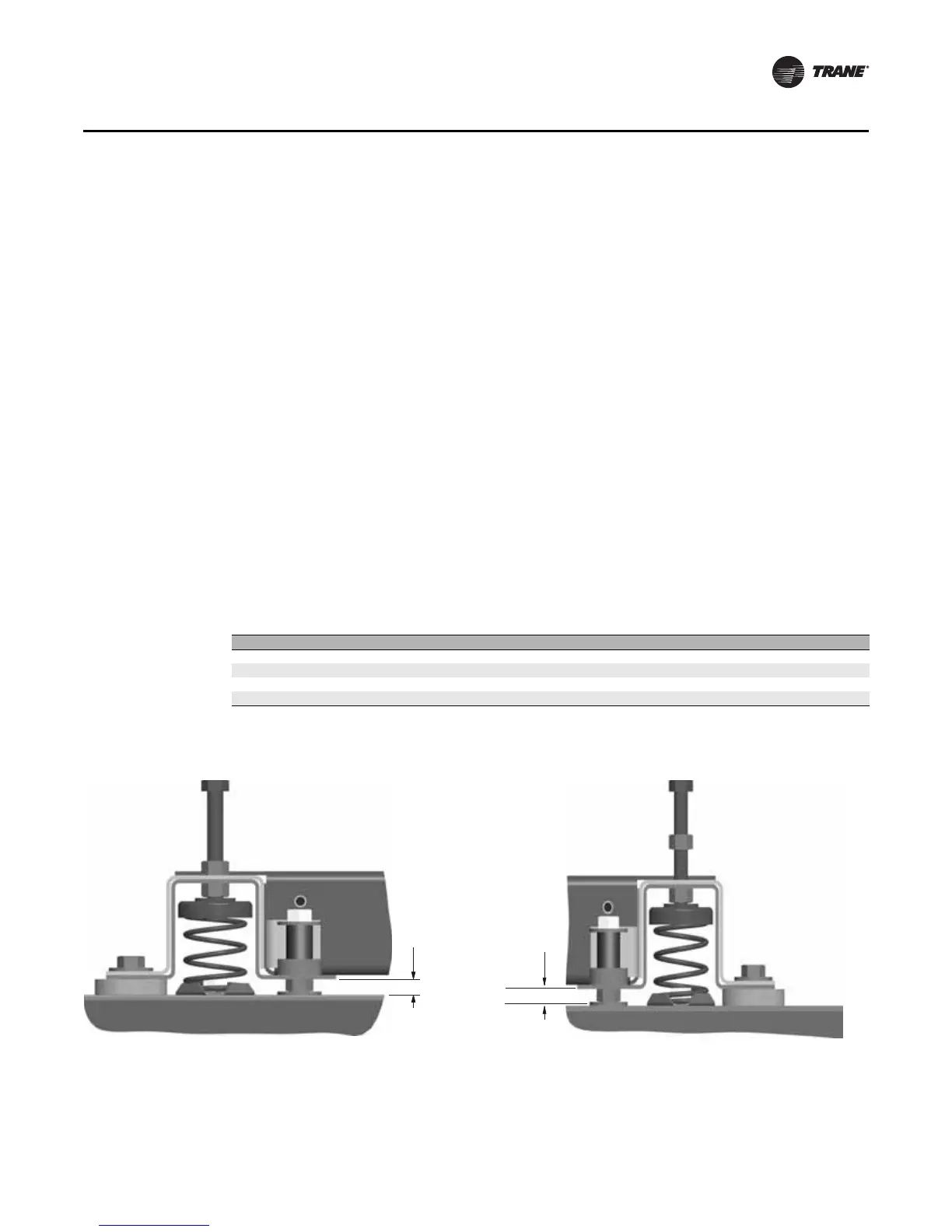
Once the shipping tie-downs are removed and the internal isolation is released, it may be necessary
to adjust the isolators to achieve the proper operation height of the fan and motor isolation base.
Minimum required clearances are listed in Table 9. To determine the isolator clearances on all unit
sizes, measure between the top of the cabinet channel and the bottom of the isolation base channel.
See Figure 51, Figure 52, Figure 53, and Figure 54.
Table 9. Minimum isolator clearances (inches)
Unit Size Fan Type Required Clearance
3–8 FC, BC, Plenum 1.0
10–30 FC, AF, Plenum 0.5
35-57 FC, AF, Plenum 0.5
66-120 FC, AF, Plenum 1.0
Figure 51. Isolator tie-down removal for unit sizes 3-8 Figure 52. Isolator tie-down removal for unit sizes 10-30
 Loading...
