42 CLCH-SVX07C-EN
Installation - Mechanical
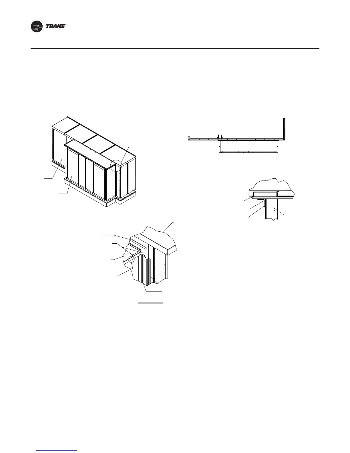
9. Install inside corner cap. See Figure 30 Detail A and B.
10. Install 3/8-inch x 3/8-inch white butyl tape to unit wall where pipe cabinet roof connects.
11. Lift pipe cabinet roof into place and attach to unit wall with screws. See Figure 30.
Outdoor Unit Weather Hood(s)
1. Per the unit drawing determine mounting location of the unit weather hoods.
2. Using the factory provided screws mount the weather hoods to the unit.
3. On larger units, weather hoods may be large enough to require angled down supports. In those
cases, the angles are shipped attached to the hood but will need to be connected to the air
handler by the installing contractor. See Figure 31.
Note: It is required that the hoods be sealed to the unit using factory-provided butyl/caulk tape.
Figure 30. Pipe cabinet
TOP VIEW
A
DETAIL A
DETAIL B
See Detail B
AHU
Pipe Cabinet
Ribbed Butyl tape
Screw 10-16 x .750 self-driller
Pipe cabinet outer roof
Slots provided to allow
final adjustment of outer roof
AHU outdoor roof
Inside corner cap
Ribbed Butyl tape
(see Note 1)
Roof and base parts
removed for clarity
Ribbed Butyl tape
Ribbed Butyl tape
(see Note 1)
Inside corner cap
Pipe cabinet wall
Note:
1. Seam to be sealed with three-ribbed Butyl tape
prior to attaching inside corner cap with screws
(10-16 x .750 self-driller).
 Loading...
