30 CLCH-SVX07C-EN
Installation - Mechanical
Unit Assembly
Note: Air handlers often include optional factory-provided casing penetration entry points for
field-provided wiring. Consider overall unit serviceability and accessibility before
mounting, running wires (power), making cabinet penetrations, or mounting any
components to the cabinet.
See “Component Installation Requirements” on page 49 for special assembly/installation
considerations.
Removing the Shipping Skid
Remove the wooden shipping blocks, wooden toe cleat if there is one, and end cleats prior to
lowering unit into final position or installing the unit to the roof curb.
Ceiling Suspension for Indoor Air Handlers Sizes 3-57
Note: Ceiling suspension is not recommended for units larger than size 57 unless using a field-
provided mounting frame.
Using a Field-Provided Mounting Frame
WARNING
Heavy Objects!
If a field-provided mounting frame is used for ceiling suspension, the installer/contractor must
provide a ceiling-suspended mounting frame designed to support the length, width, and weight
of the entire air-handling unit. Failure to use proper mounting frame, structural channels, and
hangers could result in unit falling from its mounting location which could result in death or
serious injury.
See “Unit Dimensions and Weights” on page 16 for approximate weights.
Note: It is the building engineer’s responsibility to size the structural channels and to provide the
appropriate hangers.
Structural channels in a field-provided frame can be mounted parallel to airflow or perpendicular
to airflow:
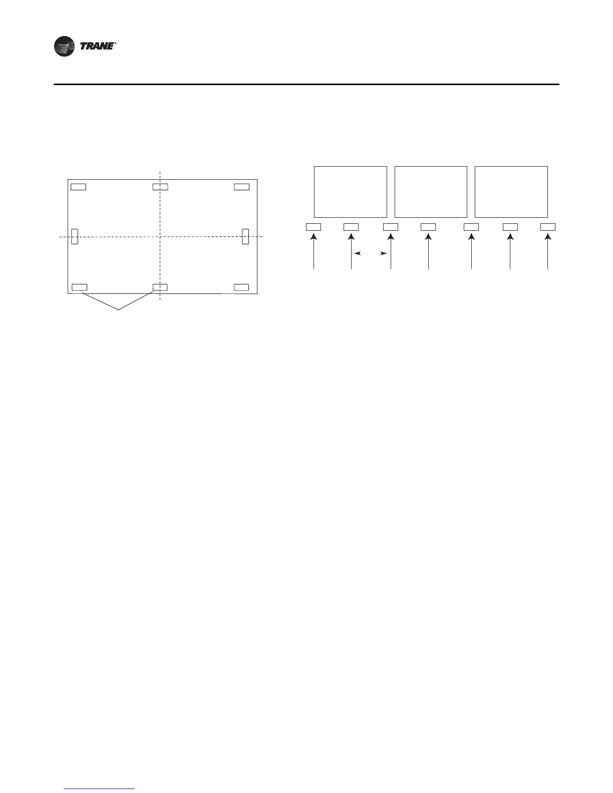
Figure 11. Piers located in each corner and spaced
evenly every four feet
Figure 12. Side view with two shipping splits - locate one
pier directly under each shipping split
Note: Piers beneath shipping splits must be structurally sound to support the weight of the unit.
 Loading...
