3-98 OM 25-3503 us – Edition 4.1 * * 2503_3503b340.fm
Operation
Re-equipping
Injury hazard due to modification work!
Can cause serious injury or death.
• Observe the following instructions:
• Stop the engine
• Raise the control lever base
• Re-equip attachments only with suitable tools
• Do not align components with your fingers or your hands but use suita-
ble tools – crushing hazard!
• Once you have re-equipped the attachments, or before starting work,
ensure that the attachment is safely locked with the stick and the tilt rod, or
with the Powertilt unit (option).
• Release the pressure – see chapter 3.50 Releasing the pressure on the
operating hydraulics on page 3-88
• Follow the safety instructions – see chapter 3.51 Re-equipping attachments
on page 3-89
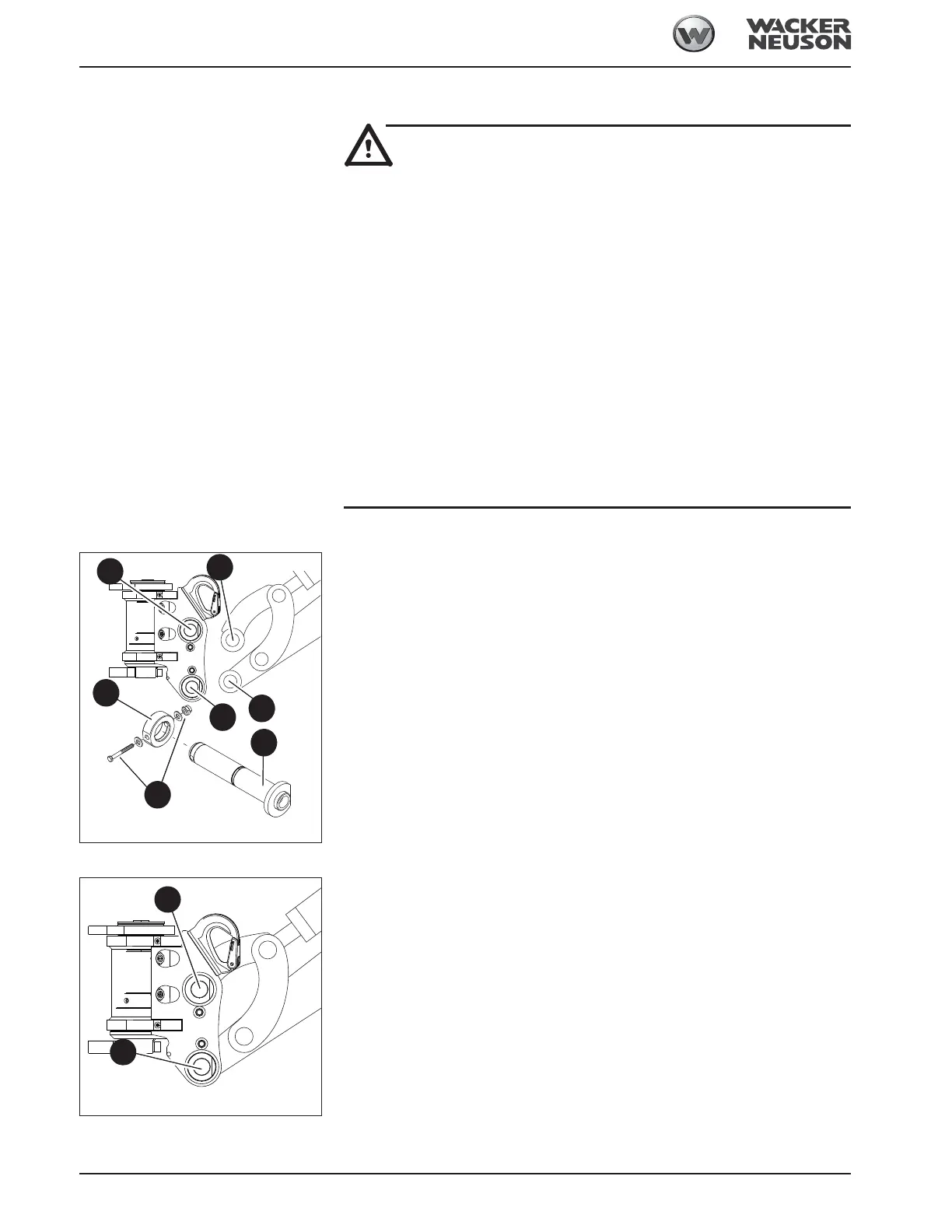
Installing the Powertilt unit
Proceed as follows:
☞ Lower the Powertilt unit to the ground with its flat side facing down
☞ Grease the joints and the pins before inserting them
☞ Start the engine
☞ Straighten the stick so that bores D and E are flush
☞ Insert greased pin F
☞ Install ring J and tighten the securing elements G
☞ Actuate the stick cylinder until bores H and I are flush
☞ Insert greased pin F
☞ Install ring J and tighten the securing elements G
Removing the Powertilt unit
Re-equip as follows:
☞ Lower the Powertilt unit to the ground with its flat side facing down
☞ Stop the engine
☞ Raise the control lever base
☞ Remove the ring and the securing elements
☞ First remove pin A, and then pin B. Carefully expel pins that are stuck with a hammer
and a brass punch
If pin A is stuck:
☞ Start the engine
☞ Slighty raise and lower the boom to take the load off the pin
☞ Stop the engine
☞ Raise the control lever base
Fig. 229: Assembly
D
F
E
H
I
G
J
Fig. 230: Removing
A
B
 Loading...