Functional Verification Procedure Functional Verification
Service Manual 26 Vital Signs Monitor Series 300
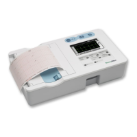
Printer
1. Put the monitor into Service Mode.
2. Verify that the printer has paper.
3. Press . Verify that a settings report prints, and that it contains no printed anomalies and
no missing or faded sections.
4. After 2 seconds of printing, verify that the current draw is no more than 2.5A above the
baseline current recorded in step 2 of the Baseline Current Draw verification test
(page 21).
5. Exit the Service Mode.
With a new roll of paper, the first line might be faded. This does not indicate a
problem.
The settings report (as shown in the example on page 26) contains a
calibration record, user record, hardware status record, and software versions
record.
• The calibration record includes manufacturing configuration data: monitor
serial number, set parameters, and language.
• The user record includes user-configurable settings: alarm limits, patient
type, parameter modes/units, auto interval, tone volume, and others.
• The hardware status record shows the hardware revision number, the
battery voltage level, the total number of NIBP monitoring cycles
completed on the monitor, and the total number of hours of operation of
the monitor.
• The software versions record indicates the software version numbers of
the main board, SpO
2
and Temperature options (if present), and NIBP.
 Loading...