Disassembly Procedure Disassemble the SpO
2
Assembly
Vital Signs Monitor Series 300 71 Service Manual
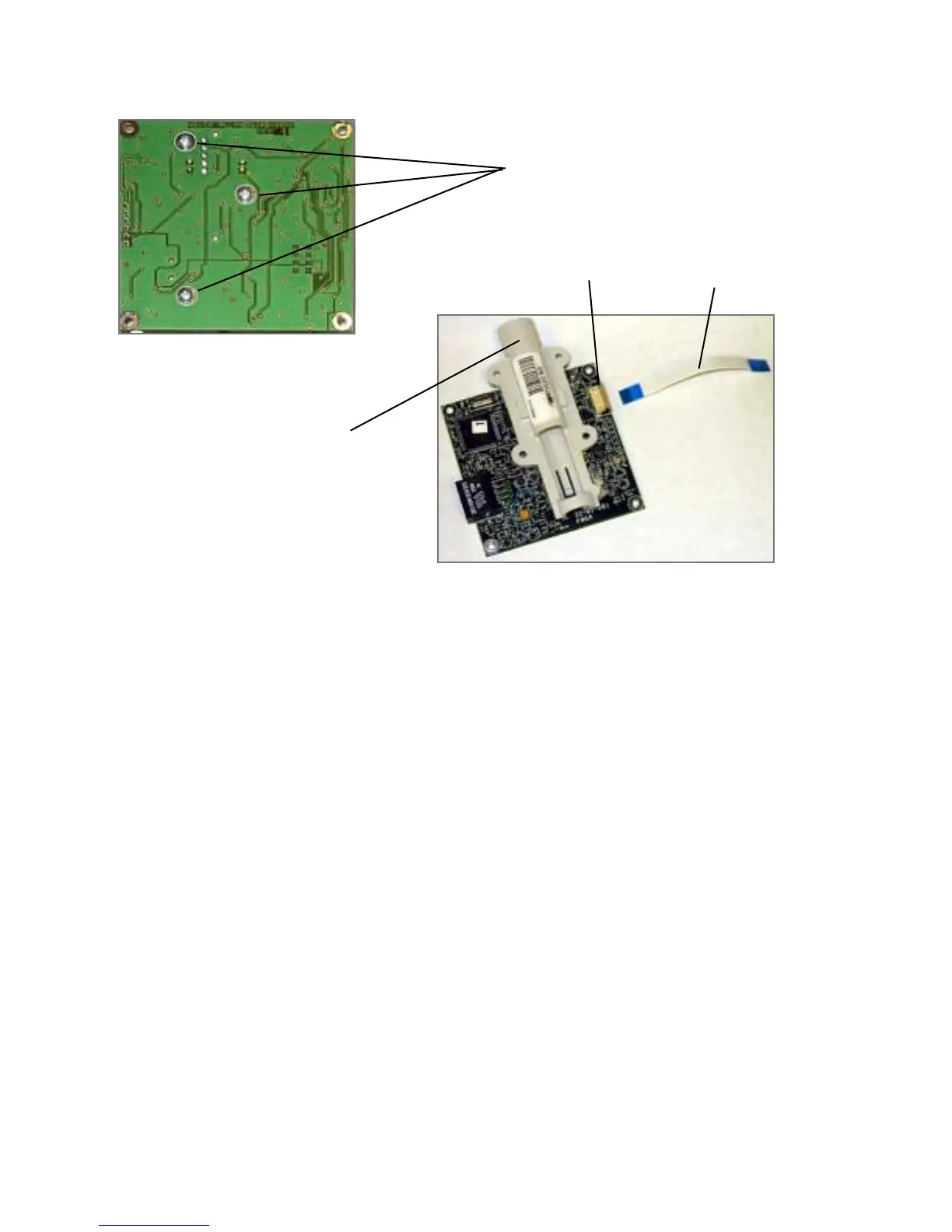
Temperature Module Reassembly Notes
To install the temperature board in the module housing:
1. Square the circuit board in the housing to fit the probe-well receiver into the top of the
outside housing.
2. Tilt the board and rotate it counterclockwise so that the temperature cable connector (J5)
fits down into the connector slot in the housing.
Disassemble the SpO
2
Assembly
1. Remove the SpO
2
assembly from the rear chassis and disassemble it as follows:
a. Remove the four screws (located on the inside of the rear chassis on the right side)
securing the SpO
2
assembly to the rear chassis.
3 screws securing the
temperature probe-well
housing
Temperature
cable
Temperature probe-well housing
ZIF connector
 Loading...