5/2011
6-13
Phaser 4600/4620 Printer Service Manual
GP 11, GP 12
General Procedures/Information
Revision - Xerox Internal Use Only
GP 11 How to Check a Sensor
Use this procedure to check the operation of all types of sensor.
NOTE: Some sensors have a resistor within the sensor and other sensors require a resistor on
the PWB. The resistor limits the current through the LED. The voltage to the sensor LED with
an external resistor, is typically 1.2V.
NOTE: The voltages, PJ numbers, pin numbers and PWB names shown are examples only.
Go to the wiring diagram associated with the RAP for the correct information.
NOTE: In some cases, two sensors are used to form an interruptible beam of light. In these
cases, the LED of one sensor and the sensing element of the other sensor are used. Treat the
two sensors as if they were housed in the same body for diagnostic purposes, ignoring the
unused part of each sensor. If the combined sensors do not operate correctly and the beam
path is clear of obstruction, it may be necessary to install both new sensors.
Quick Sensor Check
Enter the component control code for the sensor, refer to dC330. Actuate the sensor. If the dis-
play changes, the sensor operates correctly. If the display does not change, perform the proce-
dure.
Procedure
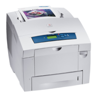
For the sensor in the wiring diagram shown in Figure 1:
1. Actuate the sensor and check for a change in voltage at PJ24, pin 2. If the voltage
changes, install a new PWB. If the voltage does not change, continue to the next step.
2. Disconnect PJ25. Check for +3.3V and 0V (GND) on the harness.
3. Disconnect PJ24 and PJ25. Check the harness and the connectors for continuity.
4. Check for +3.3V and 0V (GND) at the PWB.
5. If necessary, install new components or repair the wiring.
Figure 1 Example Sensor Wiring Diagram
GP 12 How to Check a Solenoid or Clutch
Use this procedure to check a clutch or solenoid.
Initial Actions
WARNING
Switch off the electricity to the machine. Disconnect the power cord from the customer
supply while performing tasks that do not need electricity. Electricity can cause death or
injury. Moving parts can cause injury.
1. For a clutch, check that the shafts, gears, rolls etc., associated with the clutch are free to
rotate, clean and lubricated where applicable.
2. For a solenoid, check that the solenoid is free to actuate and that the mechanisms associ-
ated with the solenoid are free to move.
Procedure
NOTE: The voltages, PJ numbers, pin numbers and PWB names shown are an example only.
Go to the wiring diagram associated with the RAP for the correct information.
NOTE: When a solenoid is energized in diagnostics, movement is seen. When a clutch is ener-
gized in diagnostics, the sound of the clutch action is heard. If possible, run the motor con-
nected to the clutch to confirm when the clutch is energized
1. Enter the dC330 output code for the clutch or solenoid. If the clutch or solenoid does not
energize, continue with step 2.
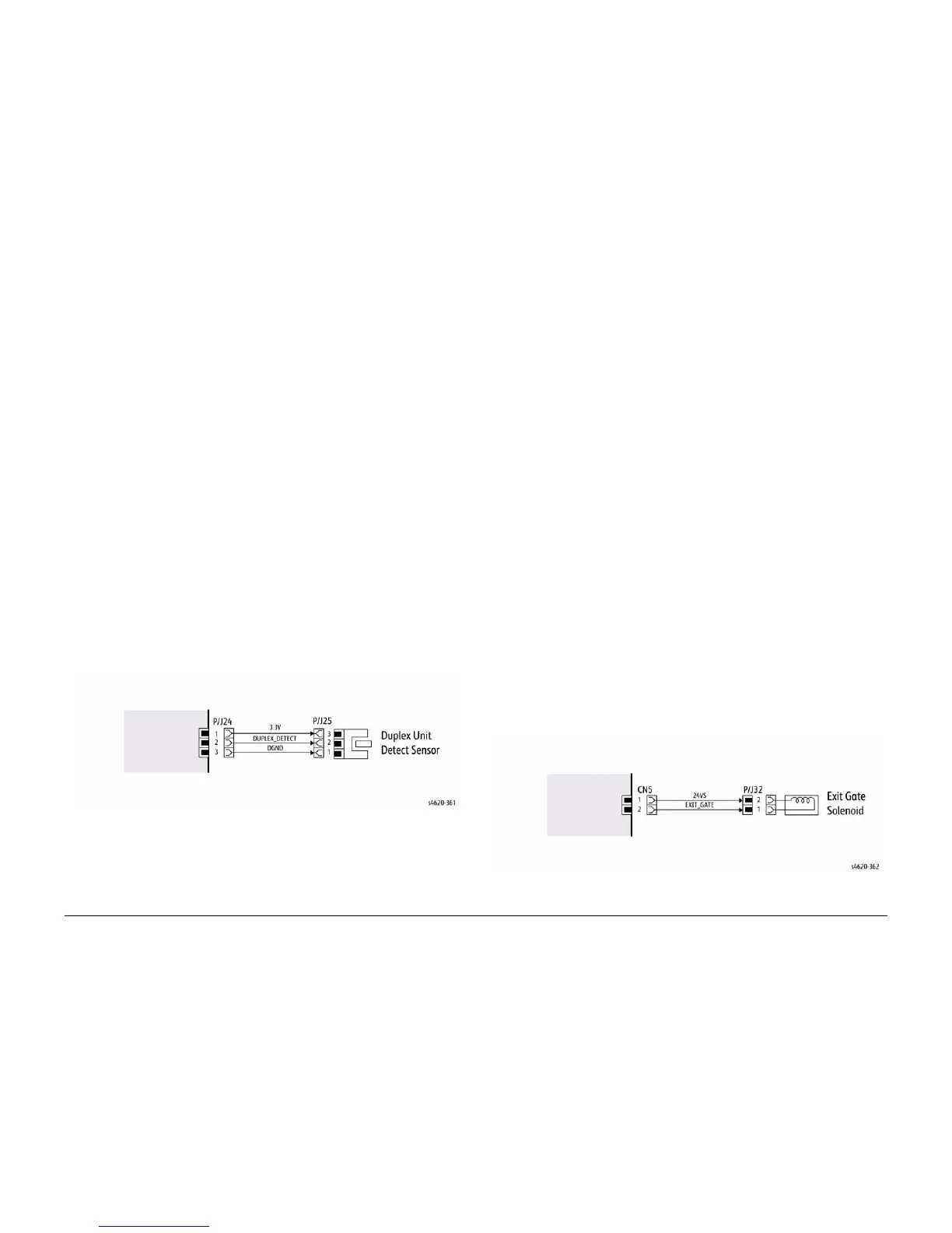
2. Figure 1, disconnect PJ32, check for +24V at PJ32 pin 2 on the wiring side of the connec-
tor, If the voltage is not correct, trace the faulty component.
3. Reconnect PJ32, enter the dC330 output code for the clutch or solenoid, while measuring
the voltage between CN1 pin 1 and the machine frame. If the voltage does not change
when the code is entered, Install a new PWB.
4. There may be an intermittent fault, perform the actions that follow:
a. Check the wiring. Repair or install new components as necessary.
b. Operate the clutch or solenoid under normal running conditions. If the clutch or sole-
noid operates intermittently or with hesitation, install new parts.
c. Check that the clutch or solenoid has enough drive to operate the mechanism to
which it is attached, if necessary install a new clutch or solenoid.
Figure 1 Example Clutch Wiring Diagram
 Loading...