5/2011
8-3
Phaser 4600/4620 Printer Service Manual
Phaser 4600/4620 Operational Overview
Principles of Operation
Revision - Xerox Internal Use Only
Phaser 4600/4620 Operational Overview
The Phaser 4600/4620 base configuration combines a monochrome laser print engine with a
multi-purpose Tray 1 (bypass) and 1 universal media tray, Tray 2. The Output Tray holds 500
20lb. sheets facedown. Phaser 4600/4620 options add memory, media capacity, and function-
ality. For models not originally equipped, a 160 GB Hard Drive is available. A memory upgrade
raises the installed RAM to the 768 MB maximum. Additional media capacity is also available.
Trays 3, 4 and 5 (520-Sheet Feeder) when installed, add two 520-sheet universal media trays.
An optional high-capacity 2000-Sheet Feeder brings the maximum paper capacity to 3,660
sheets. On the output side, 500-sheet stapler/stacker and 400-sheet Mailbox is available.
This section focuses on the printer’s operational characteristics providing detailed descriptions
of the media path, sensors, xerographics and major system assemblies.
The Printing Process
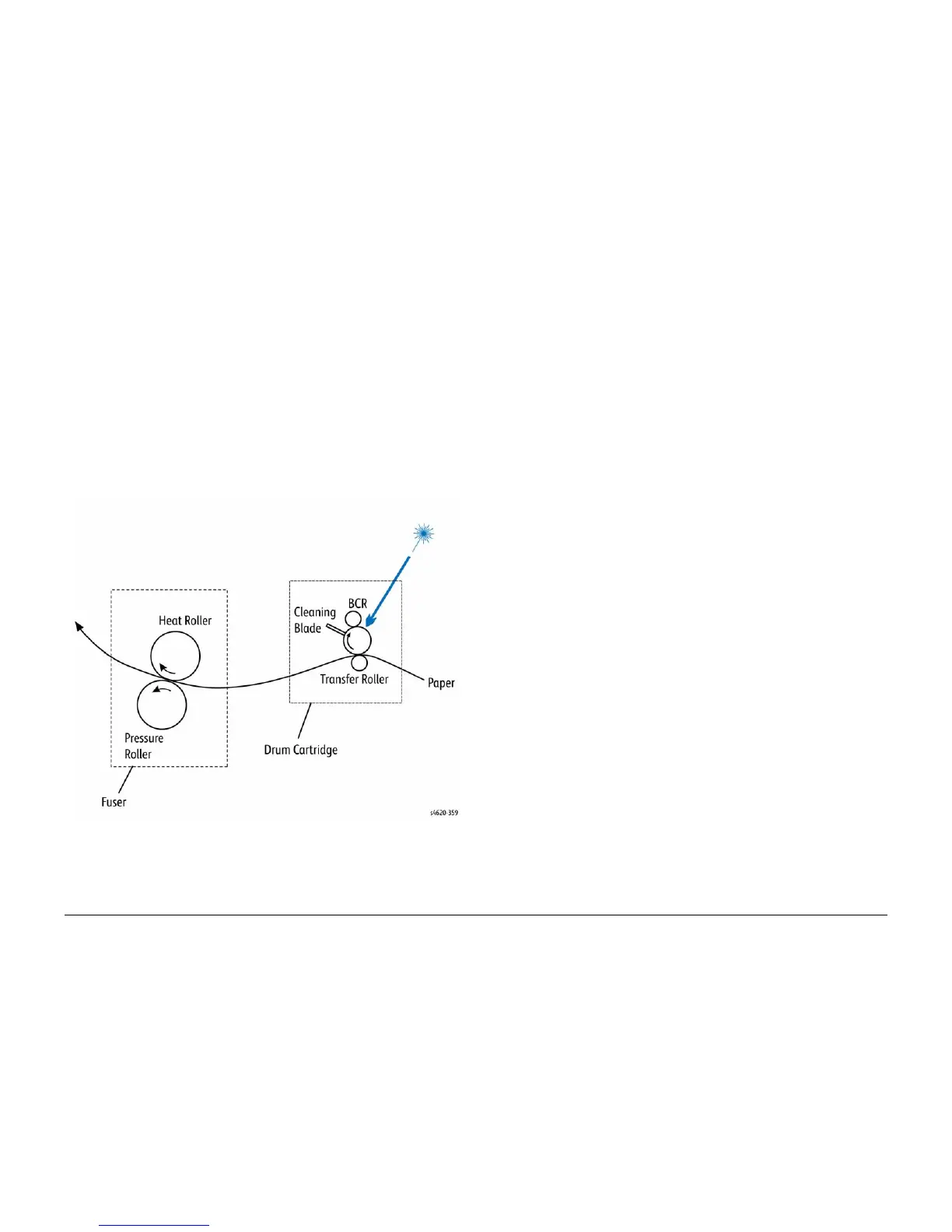
Figure 1 shows components associated with the xerographics process.
Figure 1 Xerographic process
The laser print process consists of these steps:
1. Charge – The Drum Cartridge contains a bias charge roller that uniformly distributes a
negative electrical charge over the photoconductive (OPC) drum surface.
2. Exposure – The Laser Unit scans the surface of the OPC drum located inside the Drum
Cartridge. The laser diode produces laser beams which are turned on and off according to
a data signal. A multi-faceted polygonal mirror is rotated at a specified speed. The laser
beams are reflected off of the mirror and onto the drum surface through a series of lenses
and mirrors. The laser beams scan the drum surface from one end to the other, neutraliz-
ing the negative charge to create one line of a latent image on the drum surface. The
drum is rotated and the scan process is repeated.
3. The Toner Cartridge supplies toner to the Drum Cartridge. Capacity is 30,000 pages at
5% area coverage.
4. Development – A magnetic roller in the Drum Cartridge carries a thin layer of developer
and toner supplied by an agitator in the cartridge's toner compartment. The charging and
metering blade inside the cartridge applies a negative charge to the toner and spreads
the toner onto the Magnetic Roller. The negatively charged toner is transferred to the
Areas of the drum surface that have been discharged.
5. Media Transport – The Size Switch detects media length. Movable actuators located on
the tray indicate the location of the end guide. The printer uses a three-roller system to
pick paper. A DC motor raises the tray's bottom plate, along with the media stack, against
the Nudger Roller of the feeder assembly. To pick media, the Nudger Roller advances the
top sheet to the Feed and Separator Rollers. The Separator Roller prevents multi-picks.
The Feed Roller advances the paper to the Take Away Rollers, which feeds the media to
the Registration Rollers.
6. Transfer – The pressure of the Transfer Roller against the drum assists in driving the
paper through the transfer area. The Transfer Roller applies a positive charge to the rear
surface of the paper. The negatively charged toner image on the drum is attracted to the
positive charge on the rear surface of the paper, transfers the image from the surface of
the drum onto the paper.
7. Fusing – The paper is driven into the Fuser, which uses heat and pressure rolls to melt
and bond the toner onto the surface of the paper. Heat Roller fingers inside the fuser peel
off the leading edge of the paper from the Heat Roller to prevent the paper from becoming
wrapped around the drum. The Fuser Exit Sensor detects paper exiting the fuser.
8. Cleaning – A cleaning blade in the Drum Cartridge scrapes off toner remaining on the
drum surface after Transfer has occurred. Then, the latent charge pattern remaining on
the photoconductive drum is neutralized to prepare the drum for the next exposure cycle.
9. Exit – The media advances upward into the exit rollers and into the selected output tray.
Two-sided printing reverses the direction of media through the Duplex Unit rollers and
back to the Registration Rollers. Two sensors within the IOT detect the presence and
position of media during duplex operation.
 Loading...