5/2011
6-14
Phaser 4600/4620 Printer Service Manual
GP 13, GP 14
Revision - Xerox Internal Use Only
General Procedures/Information
GP 13 How to Check a Switch
Use this procedure to check the operation of a switch.
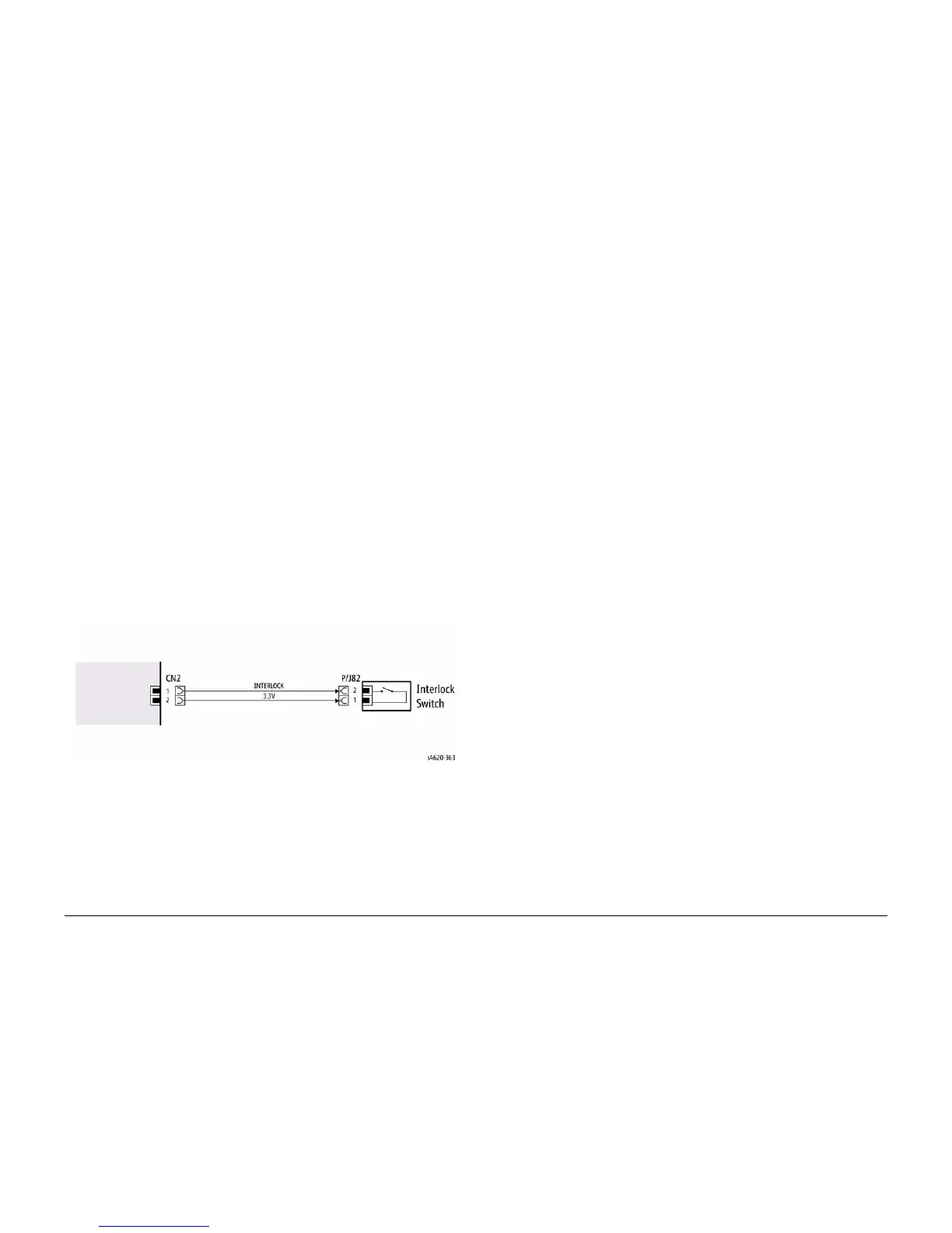
NOTE: Figure 1 shows an interlock switch actuated by the closing of a door.
Initial Actions
WARNING
Switch off the electricity to the machine. Disconnect the power cord from the customer
supply while performing tasks that do not need electricity. Electricity can cause death or
injury. Moving parts can cause injury.
Manually check that the switch operates. Ensure that the magnet or other actuator has enough
mechanical movement to operate the switch.
NOTE: The voltages, PJ numbers, pin numbers and PWB names shown are an example only.
Go to the wiring diagram associated with the RAP for the correct information.
Procedure
1. Enter diagnostics and check the switch. The switch is operating correctly, check and
adjust the mechanism that actuates the switch
2. Refer to Figure 1, then disconnect T072.
3. +5V is available between pin 1 and pin 2 on the wiring side of the connector.
4. +5V is available at PJ5 between pins 3 and 4 on the PWB.
5. Check the supply voltage. If +5V is available, install a new PWB.
6. Check the wiring between PJ5 and T072. Repair or install new parts as necessary.
7. Install a new switch.
Figure 1 Example Switch Wiring Diagram
GP 14 Separate System Modules
Use this procedure to remove the Mailbox or Finisher modules from the printer.
Description
Most service procedures for finishing modules require separation of the module from the
printer. Only 1 person is required to separate the Mailbox or Finisher from the printer.
WARNING
Switch off the electricity to the machine. Disconnect the power cord from the customer
supply while performing tasks that do not need electricity. Electricity can cause death or
injury. Moving parts can cause injury.
CAUTION
Always move the printer separately from the Finisher, Mailbox, and optional trays.
1. Clear the media path and output trays.
2. Remove the output trays from the mailbox before servicing the module.
3. Lift the module to clear the support brackets.
4. Place the module on a suitable work surface to avoid damage.
5. Check the position of the option connector before module installation on the IOT.
 Loading...