5/2011
8-6
Phaser 4600/4620 Printer Service Manual
Sensors
Revision - Xerox Internal Use Only
Principles of Operation
Sensors in the Media Path
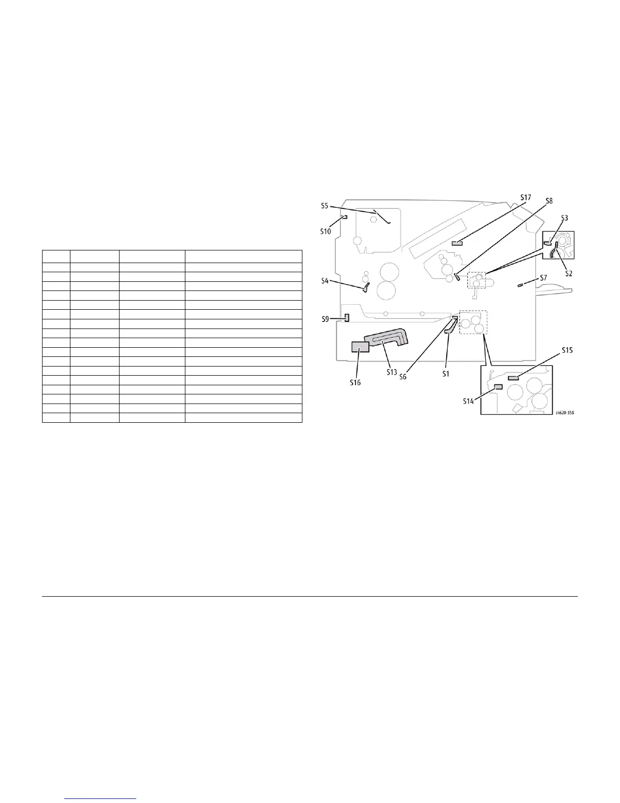
Figure 3 shows the location and designation of sensors located in the media path. Error detec-
tion is based on media transport timing through the sensing area.
Table 1 briefly describes the type and function of sensors and switches used to determine
operational status and detect jams or failures.
Media Size Sensing
Trays 2 and optional feeders detect media size using an array of microswitches (Size Switch)
mounted in the tray cavity. When the tray end guide is adjusted, the guide changes the Size
Switch actuator positions. Actuating different combinations of the Size Switch produces differ-
ent combinations of high and low signals. These signals identify what size media is loaded and
what to display on the Control Panel. Also, actuation of the Size Switch signals the tray is
present and closed to the MCU Board.
Media Present Sensing
When the last sheet is fed from any tray, the No Paper Sensor actuator drops to block the No
Paper Sensor. Feeding is inhibited until media is loaded into the tray.
Media Level Sensing
As media is fed from the tray, the media level drops. When the level reaches a certain point, an
actuator unblocks the Level Sensor signaling the control logic to raise the tray bottom plate
with the Lift Motor. Raising the tray bottom plate pushes media up to achieve optimum force
against the Nudger Roller and blocks the Level Sensor resuming paper feed. This loop contin-
ues until the No Paper sensor is activated. Paper level sensing operates the same way for
Trays 2 through 6. Tray 1 uses No Paper sensing only.
Figure 3 IOT Sensors
Table 1 List of Sensor and Interlock Functions
Number Name Type Function
S1 No paper Photo-receptive Signals no media remaining in Tray 2
S2 Registration Photo-receptive Signals leading edge at registration
S3 Feed Photo-receptive Signals leading edge registered
S4 Exit Photo-receptive Signals media present at exit
S5 Stack Full Photo-receptive Signals output tray full
S6 Duplex Photo-receptive Signals media present
S7 No paper Photo-receptive Signals no media remaining in Tray 1
S8 ADC Photo-reflective Monitors Toner density
S9 Duplex Photo-receptive Signals media present (leading edge)
S10 Rear Door Microswitch Signals Rear Door open
S11 Port open Photo-receptive Signals Waste Toner Cartridge installed
S12 Top Door Microswitch Signals Top Door open
S13 Size Switch Microswitch Signals media size in tray
S14 Pick Photo-receptive Signals Pick Assembly position
S15 Level Photo-receptive Signals lift motor to raise tray bottom
S16 Environmental pcb Monitors temperature and humidity
S17 Internal temp Thermistor Monitors internal temperature