56 www.xilinx.com VC707 Evaluation Board
UG885 (v1.4) May 12, 2014
Chapter 1: VC707 Evaluation Board Features
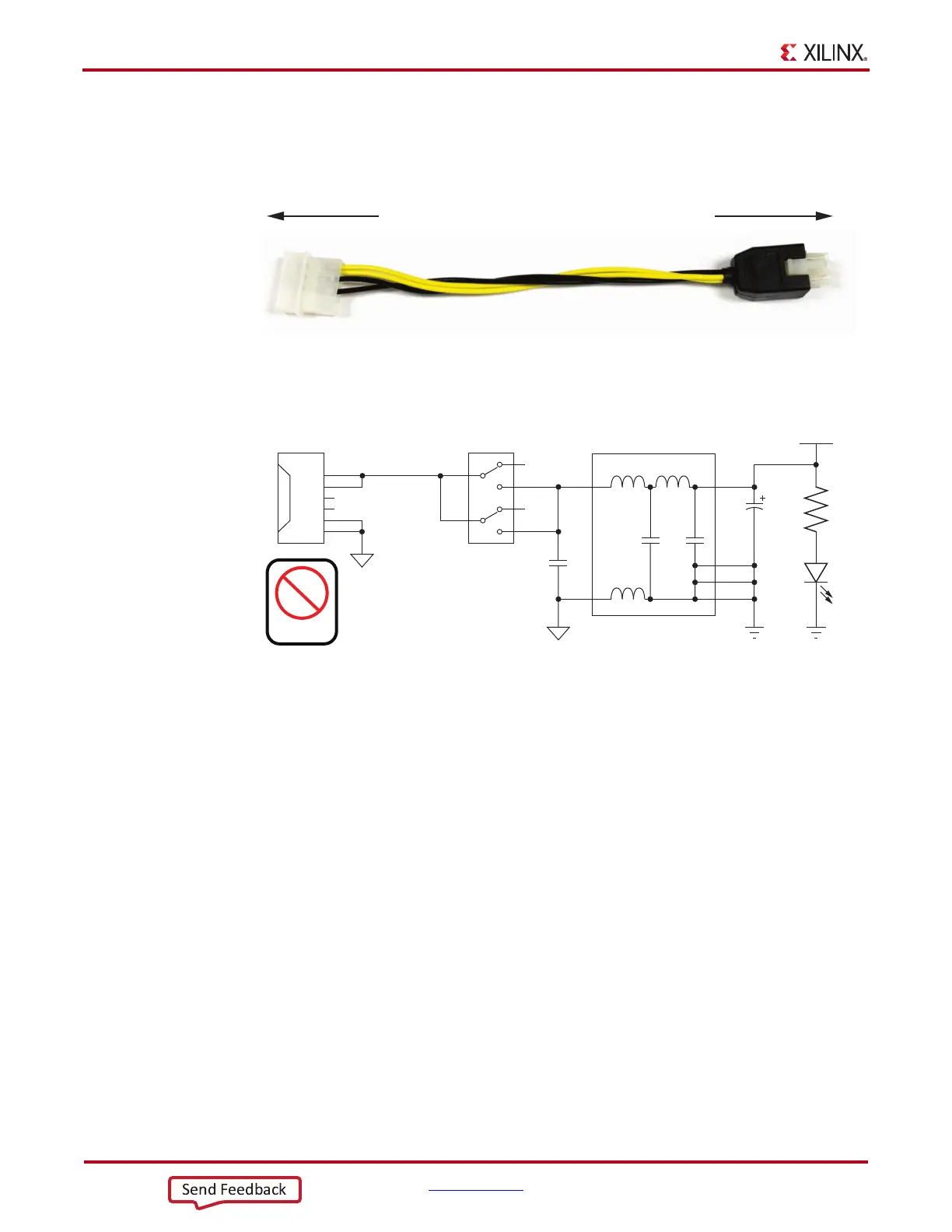
The VC707 Evaluation Kit provides the adapter cable shown in Figure 1-29 for powering
the VC707 board from the ATX power supply 4-pin peripheral connector. The Xilinx part
number for this cable is 2600304, and is equivalent to Sourcegate Technologies part number
AZCBL-WH-1109-RA4.
Figure 1-30 shows the power connector J18, power switch SW12 and indicator LED DS16.
FPGA_PROG_B Pushbutton SW9 (Active-Low)
[Figure 1-2, callout 28]
Switch SW9 grounds the FPGA's PROG_B pin when pressed. This action initiates an FPGA
reconfiguration. The FPGA_PROG_B signal is connected to FPGA U1 pin AJ11.
See 7 Series FPGAs Configuration User Guide (UG470) [Ref 2] for further details on
configuring the 7 series FPGAs.
Figure 1-31 shows SW9.
X-Ref Target - Figure 1-29
Figure 1-29: ATX Power Supply Adapter Cable
X-Ref Target - Figure 1-30
Figure 1-30: Power On/Off Switch SW15
UG885_c1_26_030512
To ATX 4-Pin Peripheral
Power Connector
To J18 on VC707 Board
UG885_c1_27_030512
VCC12_P_IN
VCC12_P
R279
1kΩ
1%
INPUT_GND
1
2
3
4
SW12
GND
C320
330μF
25V
C471
1μF
25V
GND
DS16
5
6
J18
1
2
3
4
5
6
12V
N/C
COM
12V
N/C
COM
INPUT_GND
Power
PCIe
U73
1
3
8
7
6
5

 Loading...


