15 UL Standards
180 YASKAWA TOEPC71061752B GA500 Drive Installation & Primary Operation
The setting value of E9-06 is the reference value for motor protection. Enter the motor rated
current written on the motor nameplate. Auto-Tuning the drive will automatically set E9-06 to
the value input for T4-07 [Motor Rated Current].
■ L1-01: Motor Overload (oL1) Protection
No.
(Hex.)
Name Description
Default
(Range)
L1-01
(0480)
Motor Overload
(oL1) Protection
Sets the motor overload protection with electronic thermal
protectors.
Determined by
A1-02
(0 - 6)
This parameter enables and disables the motor overload protection with electronic thermal
protectors.
The cooling capability of the motor changes when the speed control range of the motor changes.
Use an electronic thermal protector that aligns with the permitted load characteristics of the
motor to select motor protection.
The electronic thermal protector of the drive uses these items to calculate motor overload
tolerance and supply overload protection for the motor:
• Output Current
• Output Frequency
• Motor thermal characteristics
• Time characteristics
If the drive detects motor overload, the drive will trigger an oL1 [Motor Overload] and stop the
drive output.
Set H2-01 = 1F [Term MA/MB-MC Function Selection = Motor Overload Alarm (oL1)] to set a
motor overload alarm. If the motor overload level is more than 90% of the oL1 detection level,
the output terminal activates and triggers an overload alarm.
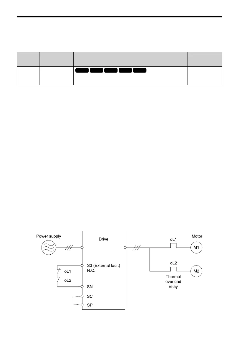
0 : Disabled
Disable motor protection when motor overload protection is not necessary or when the drive is
operating more than one motor.
Refer to Figure 15.2 for an example of the circuit configuration to connect more than one motor
to one drive.
Figure 15.2 Protection Circuit Configuration to Connect More than One Motor to One Drive

 Loading...


