10 Drive Start-Up
78 YASKAWA TOEPC71061752B GA500 Drive Installation & Primary Operation
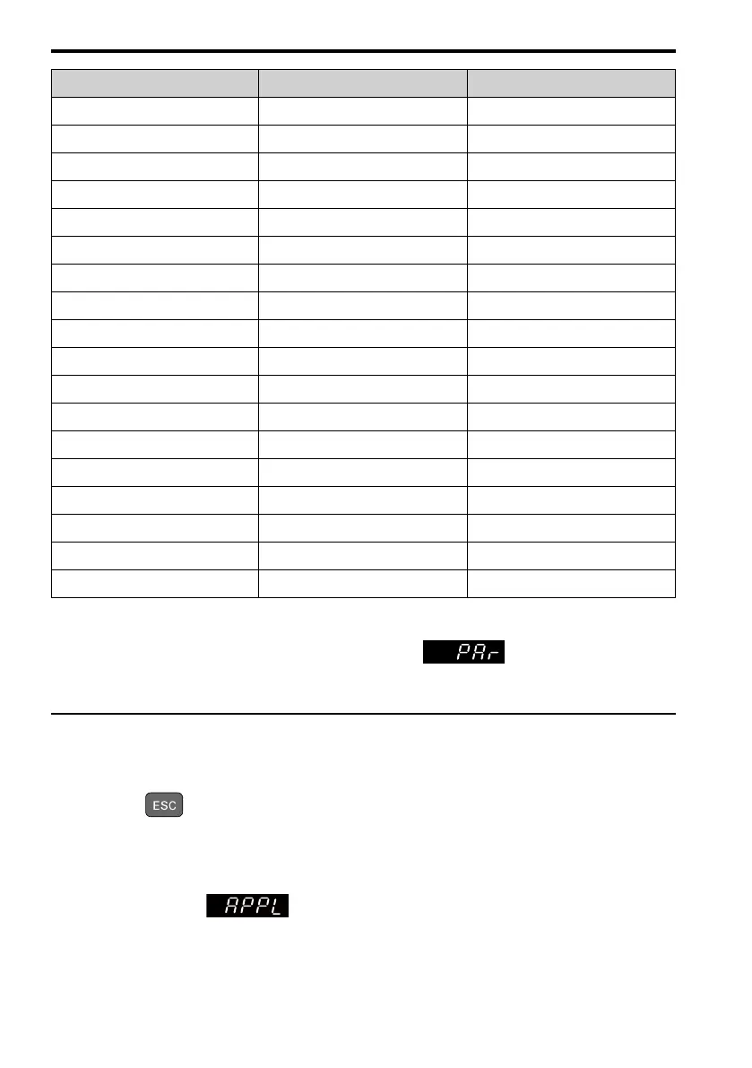
User Parameter Parameter Name
A2-09 d1-01 Reference 1
A2-10 d1-02 Reference 2
A2-11 d1-03 Reference 3
A2-12 d1-04 Reference 4
A2-13 d1-17 Jog Reference
A2-14 E1-01 Input AC Supply Voltage
A2-15 E1-03 V/f Pattern Selection
A2-16 E1-04 Maximum Output Frequency
A2-17 E1-05 Maximum Output Voltage
A2-18 E1-06 Base Frequency
A2-19 E1-09 Minimum Output Frequency
A2-20 E1-13 Base Voltage
A2-21 E2-01 Motor Rated Current (FLA)
A2-22 E2-04 Motor Pole Count
A2-23 E2-11 Motor Rated Power
A2-24 H4-02 Terminal AM Analog Output Gain
A2-25 L1-01 Motor Overload (oL1) Protection
A2-26 L3-04 Stall Prevention during Decel
Note:
• When you change A1-02 [Control Mode Selection], the settings of some parameters automatically change.
• This manual also shows parameters that are not in Setup Mode. Use to set the parameters not shown
in the Setup Mode.
• Display parameters change when the A1-06 [Application Preset] setting changes.
◆ Set and View Necessary Parameters
Show the frequency reference screen.
Note:
Push and hold to return to frequency reference screen from any screen.
The setup mode shows the parameters set in A2-01 to A2-32 [User Parameter 1 to User
Parameter 32]. This lets you quickly access and change these parameters.
Note:
Setup mode always shows (A1-06 [Application Preset]) at the top of the list. When you change the
setting, the settings for A2-01 to A2-32 change.

 Loading...


