8 Electrical Installation
58 YASKAWA TOEPC71061752B GA500 Drive Installation & Primary Operation
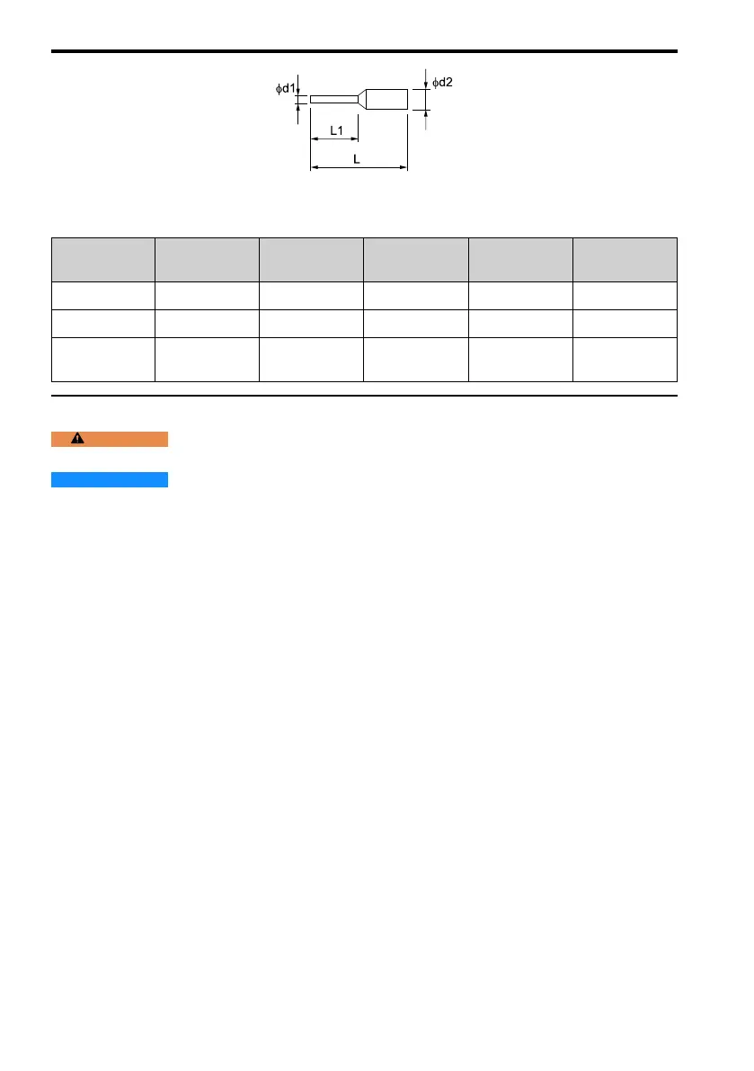
Figure 8.9 External Dimensions of Crimp Ferrules
Table 8.10 Crimp Ferrule Models and Sizes
Wire Gauge
mm
2
(AWG)
Model L (mm) L1 (mm) φd1 (mm) φd2 (mm)
0.25 (24) AI 0.25-8YE 12.5 8 0.8 2.0
0.34 (22) AI 0.34-8TQ 12.5 8 0.8 2.0
0.5 (20)
AI 0.5-8WH,
AI 0.5-8OG
14 8 1.1 2.5
◆ Wiring the Control Circuit Terminal
WARNING
Electrical Shock Hazard. Do not remove covers or touch circuit boards while the drive is
energized. If you touch the internal components of an energized drive, it can cause serious injury or death.
NOTICE
Do not let wire shields touch other signal lines or equipment. Insulate the wire shields with
electrical tape or shrink tubing. If you do not insulate the wire shields, it can cause a short circuit and damage the
drive.
Note:
• Use a Class 2 power supply to connect external power to the control terminals. If the power supply for peripheral
devices is incorrect, it can cause a decrease in drive performance.
• Connect the shield of shielded cable to the applicable ground terminal. Incorrect equipment grounding can cause drive
or equipment malfunction from electrical interference.
• Isolate wiring for contact output terminals MA, MB, MC, P1, C1, P2, and C2 from other control circuit wiring.
Incorrect wiring procedures can cause the drive and connected equipment to malfunction and cause the drive to trip.
• Isolate control circuit wiring from main circuit wiring (terminals R/L1, S/L2, T/L3, L/L1, N/L2, B1, B2, U/T1, V/T2,
W/T3, -, +1, +2) and other high-power wiring. If control circuit wiring is adjacent to main circuit wiring, it can cause
incorrect operation of the drive and equipment from electrical interference.
Wire the grounding terminal and main circuit terminals, then wire the control circuit terminals.
1. Remove the front cover from the drive.
You must remove the keypad to move Jumper S5.

 Loading...


