8 Electrical Installation
62 YASKAWA TOEPC71061752B GA500 Drive Installation & Primary Operation
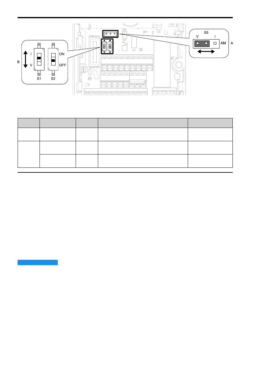
Figure 8.14 Locations of Switches
Table 8.11 I/O Terminals and Switches Functions
Position Switch Terminal Function Default
A Jumper switch S5 AM
Sets the output method for terminal AM (voltage
or current).
V (voltage output)
B
DIP switch S1 A2
Sets the input method for terminal A2 (voltage or
current).
I (current input)
DIP switch S2 -
Enables and disables the MEMOBUS/Modbus
communications termination resistor.
OFF
◆ Control I/O Connections
This section gives information about the settings for the listed control circuit I/O signals.
• MFDI (terminals S1 to S7)
• Pulse train output (terminal MP)
• MFAI (terminal A2)
• MFAO (terminal AM)
• MEMOBUS/Modbus communications (terminals D+, D-, AC)
■ Set Sinking Mode/Sourcing Mode
Close the circuit between terminals SC-SP and SC-SN to set the sinking mode/sourcing mode
and the internal/external power supply for the MFDI terminals. The default setting for the drive
is internal power supply sinking mode.
NOTICE
Damage to Equipment. Do not close the circuit between terminals SP-SN. If you close the
circuits terminals SC-SP and terminals SC-SN, it will cause damage to the drive.

 Loading...


