8 Electrical Installation
66 YASKAWA TOEPC71061752B GA500 Drive Installation & Primary Operation
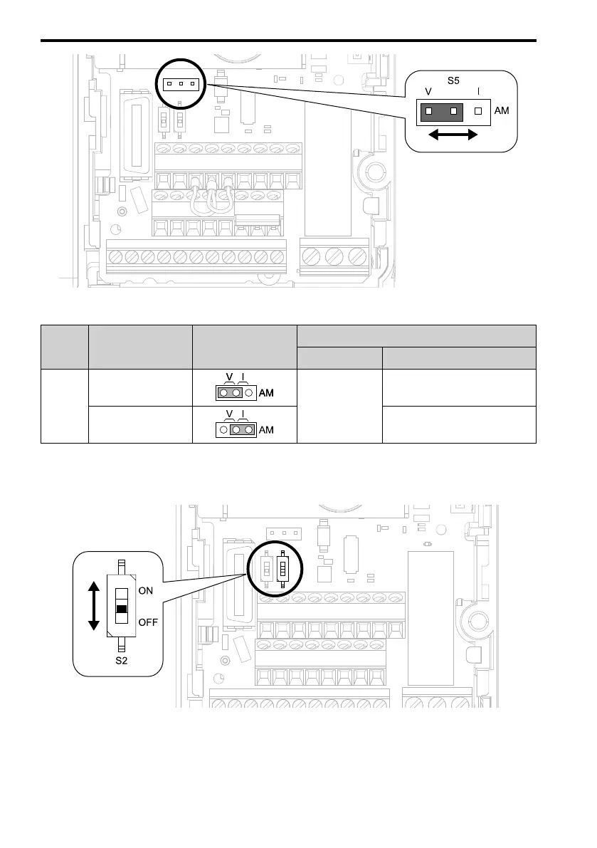
Figure 8.18 Location of Jumper Switch S5
Terminal
Types of Output
Signals
Jumper S5
Parameter
No. Signal Level
AM
Voltage output
(Default)
H4-07
0: 0 V to 10 V
Current output 2: 4 mA to 20 mA
■ Switch ON Termination Resistor for MEMOBUS/Modbus Communications
When the drive is the last slave in a MEMOBUS/Modbus communications, set DIP switch S2 to
the ON position. This drive has a built-in termination resistor for the RS-485 interface.
Figure 8.19 Location of DIP Switch S2

 Loading...


