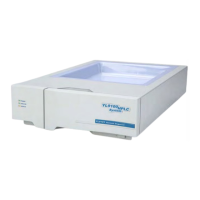
YL9170 RI Detector
If possible we recommend the addition of a small amount of organic solvent(isopropanol or
methanol).
If it is not possible to remove the contaminant from the cell it might be necessary to replace it with a new
one.
After clean or replace the flow cell reassemble the detector. Perform a measurment to check the problem
is solved.
4-6. The heating circuit of the Detector
In the following chapter the complete specification of the heating circuit is put together.
1) In the normal mode the temperatrue is displayed with one digit(e.g. 35.0
o
C). If you want a more
detailed information you can switch to the service mode where the temperature is displayed with
three digit(e.g. 35.012
o
C).
2) The temperature sensor will be detected automatically when the instrument is switched on.
3) If the heating is switched off the optical bench is operated at a temperature of about 6
o
C above
ambient tempeature due to heat irradiated of electronic components.
4) The heat cartridge has an internal resistance of 750Ω
5) If the temperatue snesor does not work or is not connected to the main board, the error message
noTS will be displayed.
6) If the current temperature of the optical bench is below 9
o
C or beyond 65
o
C, the error message
„!“ will show up and an acoustic signal occurs.
7) If the heating is not switched off properly by the firmware a thermal fuse will switch off the heating
at a temperature of 72
o
C.
L9170
17

 Loading...