EasyManua.ls Logo

YOKOGAWA Daqstation DX2020 User Manual

YOKOGAWA Daqstation DX2020
366 pages
To Next Page IconTo Next Page
To Previous Page IconTo Previous Page
Page #115 background imageLoading...
Page #115 background image
Measurement Channels and Alarms
3-17
IM 04L42B01-01E
1
2
3
4
5
6
7
8
9
10
11
12
13
App
Index
3.10 CountingPulses(/PM1Option)
The pulses applied to the pulse input terminal are counted on a computation channel.
For a description of the function, see section 1.1.
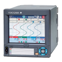
SetupScreen
Press MENU (to switch to setting mode), and select the Menu tab > Math channel >
Calculationexpression,Alarm.
SetupItems
• First-CH/Last-CH
Select the target computation channels.
• Mathrange>MathOn/Off
Select On.
• Mathrange>Calculationexpression
Enter the equation using symbols.
Q01 to Q08: Displays the number of pulses per second.
P01 to P08: Displays the number of pulses per scan interval.
* The numbers 01 to 08 correspond to the pulse input terminal numbers.
For the procedure to set the computation channels, see section 9.1.
The procedure is explained below using an example.
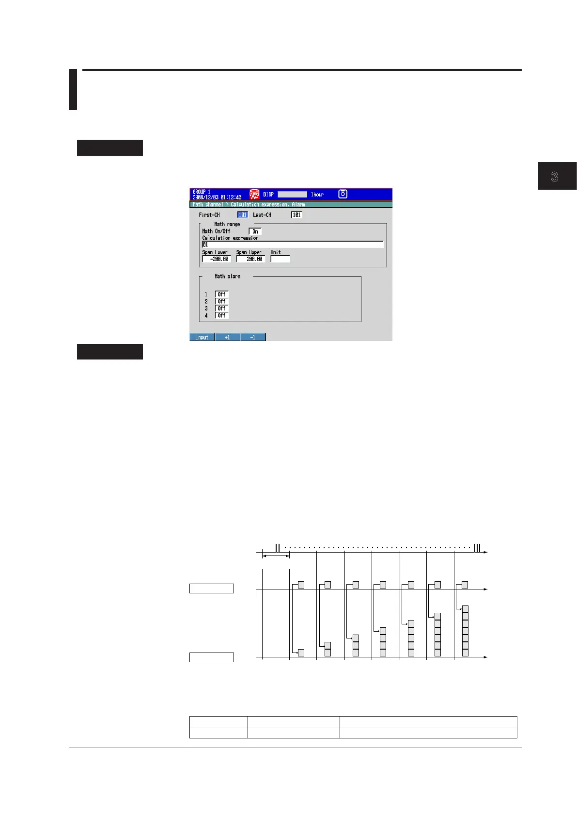
• Example1:PulseSumValue
Display the sum value of the pulse signal applied to pulse input terminal number 6.
Number of pulses
per scan interval
TLOG.SUM
Pulse sum value
Pulse input
Scan interval
Time
(Sum)
P6
 Expression
Assign the computation channel and set the expression. Set the span lower/upper
limit and unit according to the application.
101
Sum of the number of pulses per scan interval
Channel
Equation
Description
TLOG.SUM(P6)

Table of Contents

Question and Answer IconNeed help?

Do you have a question about the YOKOGAWA Daqstation DX2020 and is the answer not in the manual?

YOKOGAWA Daqstation DX2020 Specifications

General IconGeneral
BrandYOKOGAWA
ModelDaqstation DX2020
CategoryRecording Equipment
LanguageEnglish

Summary

Chapter 1 Overview of Functions

1.1 Input Section

Describes measurement channels, scan interval, and A/D converter integration time.

1.2 Alarms

Explains the alarm types, hysteresis, and delay functions.

1.4 Data Storage Function

Explains the types of data that the DX can record and how to store them.

1.6 Event Action and Remote Control Functions (/R1 and /PM1 Options)

Describes how specified actions are carried out when events occur.

1.7 Security Function

Explains the DX security functions, including key lock and login.

1.8 Computation and Report Function (/M1 and /PM1 Options)

Explains how to define equations in computation channels.

Chapter 3 Measurement Channels and Alarms

3.1 Setting the Scan Interval and the Integration Time of the A/D Converter

Selects the scan interval and A/D converter integration time.

3.3 Setting the Input Range

Sets the input range for each channel.

3.7 Setting Alarms on Channels

Sets alarms after setting the range for each channel.

3.9 Performing Calibration Correction (/CC1 Option)

Corrects input values using segments for measured values.

Chapter 4 Switching Operation Screens

4.2 Displaying the Measured Data as Waveforms, Values, or Bar Graphs

Explains how to use trend, digital, and bar graph displays.

4.3 Displaying Past Measured Data (Historical Trend Display)

Describes five methods to display past measured data.

Chapter 6 Saving and Loading Data

6.1 Setting the Recording Conditions of the Measured Data

Sets the method for recording measured data.

6.2 Setting the Method for Saving the Data

Sets the method for recording data to the storage medium.

6.9 Saving/Loading the Setup Data

Saves setup data to external storage or loads it from external storage.

Chapter 7 Customizing Actions Using the Event Action and Remote Control Functions (/R1 and /PM1 Options)

Chapter 8 Using the Security Function

8.1 Disabling the Key Operation (Key Lock Function)

Disables key operations by locking the keys.

8.2 Enabling Only Registered Users to Operate the DX (Login Function)

Allows only registered users to operate the DX.

Chapter 9 Computation and Report Functions (/M1 and /PM1 Options)

9.1 Setting the Expression, Measurement Range, Alarm, Tag, and Data Storage on Computation Channels

Sets computation channel expressions, ranges, alarms, tags, and data storage.

9.2 Writing Expressions

Explains the meaning and how to write expressions.

9.5 Creating Reports

Sets how the reports are created.

Chapter 10 Using External Input Channels (/MC1 Option)

10.1 Setting External Input Channels

Sets external input channels for external instruments.

Chapter 11 Troubleshooting

11.1 A List of Messages

Lists possible error codes and messages displayed during operation.

11.2 Troubleshooting

Provides a flowchart for troubleshooting common issues.

Chapter 12 Calibration

12.2 Calibrating the DX

Recommends annual calibration for measurement accuracy.

Chapter 13 Specifications

13.3 Data Saving Function

Details internal memory, external storage, and data formats.

Related product manuals