Operation Manual / 4 Product description / A130-H.. - A140-H
8 Dismantling and fitting / 8.18 Installing the gas outlet flange
© Copyright 2017 ABB. All rights reserved. HZTL4030_EN Revision D May 2017
8.18 Installing the gas outlet flange
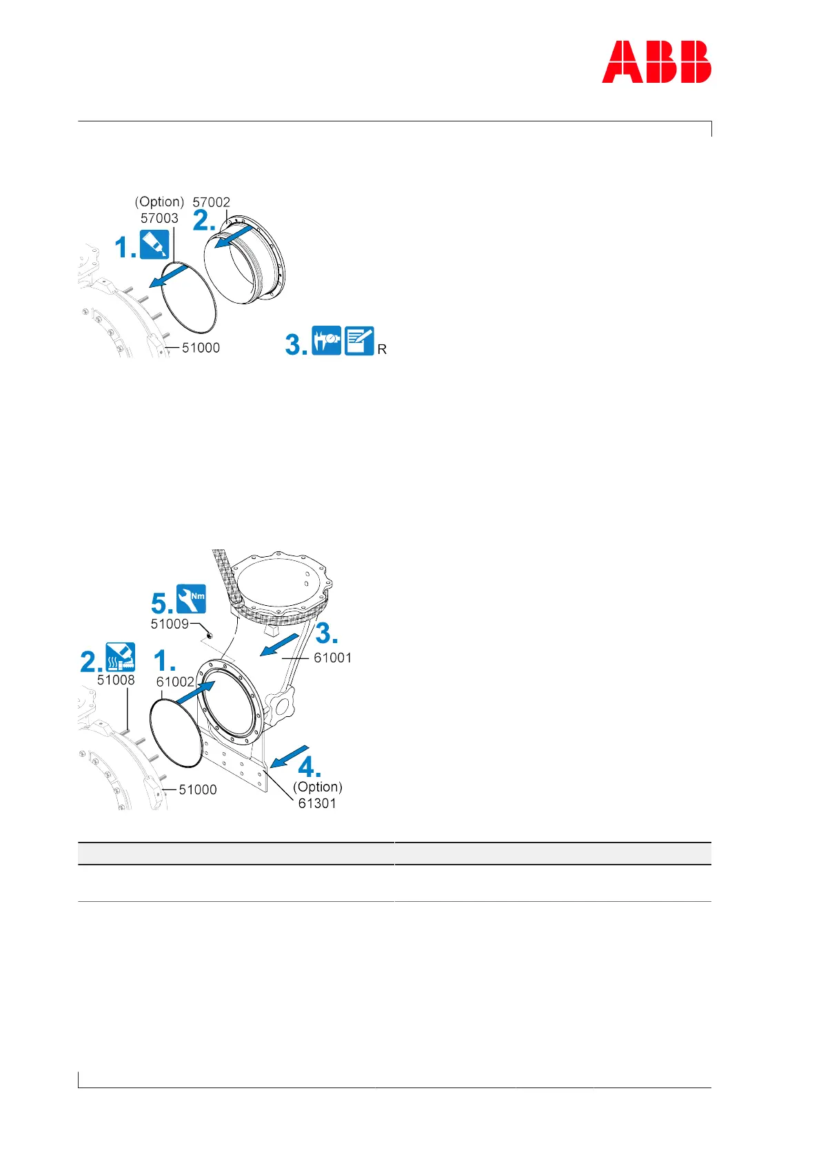
Fig.49: Installing the gas outlet flange
1. If present: Insert the metal C-ring (57003) into the turbine casing (51000) and secure with
high-vacuum grease.
2. Install the gas outlet flange (57002) in the turbine casing.
3. Measure radial clearance (R) (see chapter Radial clearances N and R).
8.19 Installing the gas outlet casing
Fig.50: Installing the gas outlet casing
Part number A130 A135 A140
51009 M8
20Nm
M10
40Nm
M12
65Nm
Table42: Tightening torque (51009)
1. Insert a new gasket (61002) into the gas outlet casing (61001).
2. Coat the threads of the studs(51008) with high-temperature grease.
3. Attach the lifting gear to the gas outlet casing (61001) and position the gas outlet casing
in the correct position on the turbine casing (51000).
4. If present: Fit the support (61301).
Page 80 / 91
 Loading...