Fieldbus control through the embedded fieldbus interface (EFB) 353
control panel mode. Make sure the jumper is on the correct position before connect to
fieldbus.
Setting up the embedded fieldbus interface (Modbus)
To take the Modbus into use
1. Select Modbus RTU from the Control macros menu (see section Submenus on
page 17).
The following parameters change automatically.
You can manually set the drive up for the embedded fieldbus communication with the
parameters shown in the table below. The Setting for fieldbus control column gives
either the value to use or the default value. The Function/Information column gives
a description of the parameter.
Parameter Setting
20.01 Ext1 commands Embedded fieldbus
20.03 Ext1 in1 Not selected
20.04 Ext1 in2 Not selected
22.11 Ext1 speed ref1 EFB ref1
22.22 Constant speed sel1 Not selected
22.23 Constant speed sel2 Not selected
23.11 Ramp set selection Acc/Dec time 1
28.11 Ext1 frequency ref1 EFB ref1
28.22 Constant frequency sel1 Not selected
28.23 Constant frequency sel2 Not selected
28.71 Freq ramp set sel Acc/Dec time 1
31.11 Fault reset selection DI1
58.01 Protocol enable Modbus RTU
...
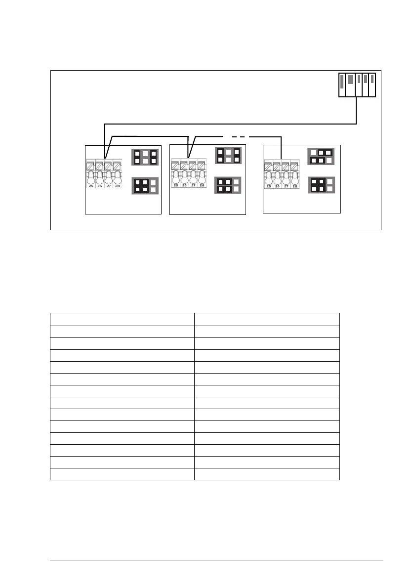
Fieldbus controller
Fieldbus
Termination ON
1)
1) The device at both ends on the fieldbus must have termination set to ON.
...
Termination OFF
Drive
Modbus Mode
Termination OFF
Drive
Modbus Mode
Termination ON
Drive
Modbus Mode
J1
J1
J1
J2
J2
J2
B+
A-
SHIELD
AGND
B+
A-
SHIELD
AGND
B+
A-
SHIELD
AGND
ACS180 FW.book Page 353 Tuesday, March 9, 2021 2:25 PM
 Loading...


