Parameters 289
97.94 IR comp max
frequency
Sets the frequency at which IR compensation (set by
parameter 97.13 IR compensation) reaches 0 V. The unit
is % of motor nominal frequency.
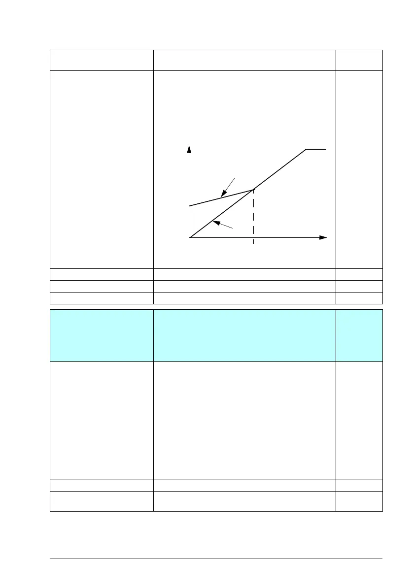
IR compensation
When enabled, IR compensation provides an extra
voltage boost to the motor at low speeds. Use IR
compensation, for example, in applications that require a
high breakaway torque.
50.0
1.0...200.0 % IR compensation maximum frequency in %. 1 = 1%
97.135 Udc ripple Calculates ripple voltage. 0.0 V
0.0…200.0 V Voltage. 1 = 1 V
98
98 User motor parameters
Motor values supplied by the user that are used in the
motor model.
These parameters are useful for non-standard motors, or
to just get more accurate motor control of the motor on
site. A better motor model always improves the shaft
performance.
98.01 User motor model
mode
Activates the motor model parameters 98.02…98.12 and
98.14.
Notes:
• Parameter value is automatically set to zero when ID
run is selected by parameter 99.13 ID run requested.
The values of parameters 98.02…98.12 are then
updated according to the motor characteristics
identified during the ID run.
• Measurements made directly from the motor terminals
during the ID run are likely to produce slightly different
values than those on a data sheet from a motor
manufacturer.
• This parameter cannot be changed while the drive is
running.
Not selected
Not selected Parameters 98.02…98.12 inactive. 0
Motor parameters The values of parameters 98.02…98.12are used as the
motor model.
1
No. Name/Value Description Default
FbEq 16
A
B
A = IR compensated
B = No compensation
f (Hz)
Motor voltage
97.13
97.94
ACS180 FW.book Page 289 Tuesday, March 9, 2021 2:25 PM

 Loading...


