80 Program features
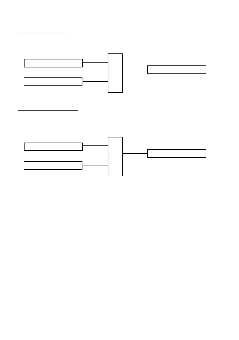
Torque trim connection
Torque trim is added at 26.75 Torque reference act 5and the final torque reference
after the trim addition is available in parameter 26.76 Torque reference act 6.
Frequency trim connection
Frequency trim is added at 28.02 Frequency ref ramp out and the final frequency
reference is generated after the trim addition. At the moment, no parameter is
available to see the final frequency reference after adding frequency trim.
Note: PID trim output auto connection is disabled in the firmware when the drive is
stopped with the 21.04 Emergency stop mode value Ramp stop (Off1) or value Eme
ramp stop (Off3). In other words, PID trim output actual (40.05 Process PID trim
output act) will not be added to the respective speed, torque and frequency reference
chains during ramp stop or emergency stop.
Mechanical brake control
A mechanical brake can be used for holding the motor and driven machinery at zero
speed when the drive is stopped, or not powered. The brake control logic observes
the settings of parameter group 44 Mechanical brake control as well as several
external signals, and moves between the states presented in the diagram on
page 81. The tables below the state diagram detail the states and transitions. The
timing diagram on page 83 shows an example of a close-open-close sequence.
Inputs of the brake control logic
The start command of the drive (bit 5 of 06.16 Drive status word 1) is the main control
source of the brake control logic.
26.75 Torque reference act 5
torque trim
26.76 Torque reference act 6
+
28.02 Frequency ref ramp out
frequency trim
final frequency reference
+
ACS180 FW.book Page 80 Tuesday, March 9, 2021 2:25 PM