Control macros 39
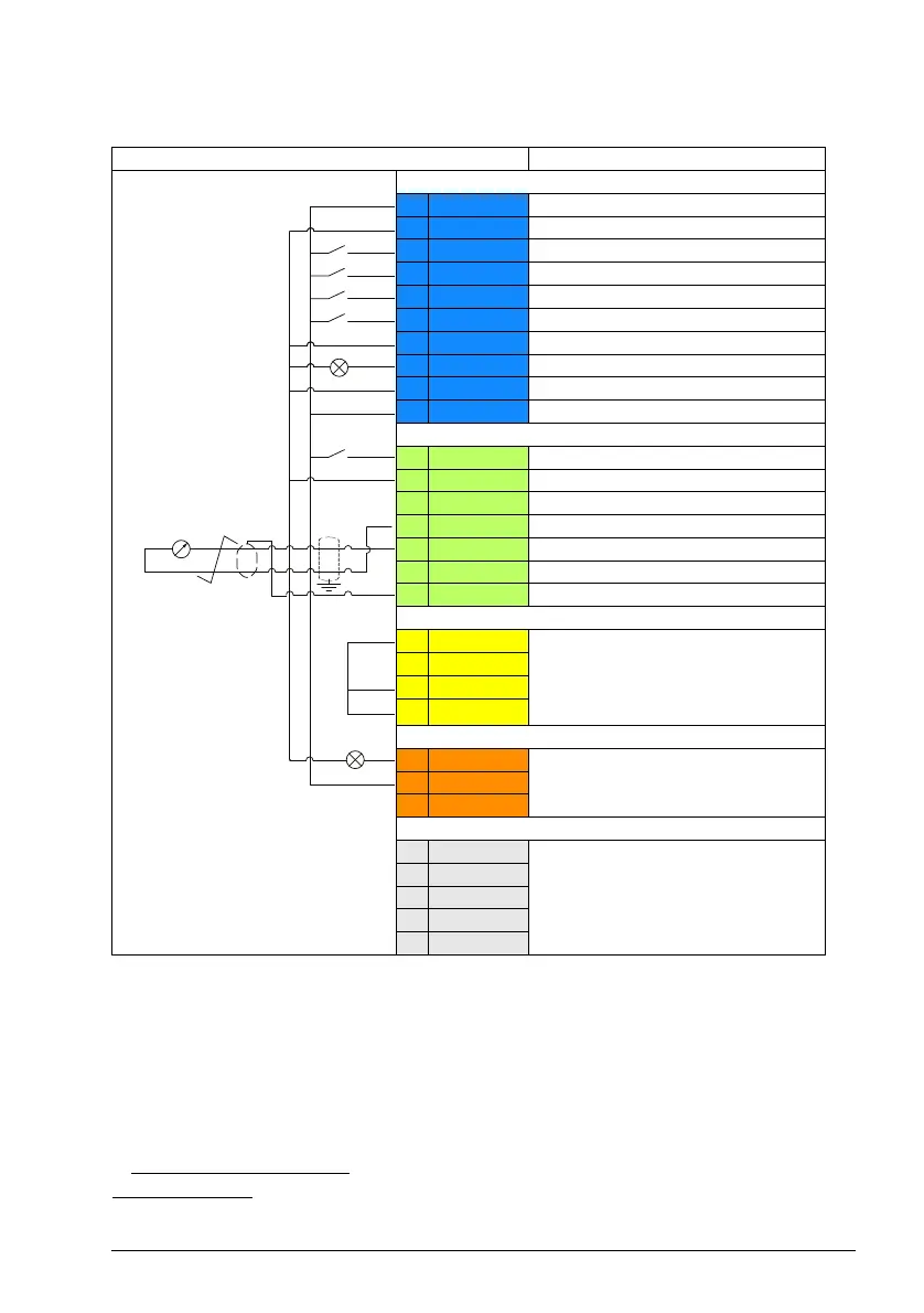
Default control connections for the Motor potentiometer macro
Terminal sizes: 0.5 mm² … 1 mm²
Notes:
1)
When the input signal is on, the speed/frequency increase or decrease along a
parameter-defined change rate. See parameters22.75, 22.76, and 22.77. If DI3 and
DI4 are both active or inactive, the frequency/speed reference is unchanged. The
existing frequency/speed reference is stored during stop and power down.
2)
In scalar control (default): See parameter group 28 Frequency reference chain.
In vector control: See parameter group 23 Speed reference ramp.
Terminals Descriptions
Digital I/O connections
21 24 V Aux. +24 V DC, max 200 mA
22 DGND Aux. voltage output common
8 DI1 Start / Stop
9 DI2 Forward / Reverse
10 DI3 Speed reference up
1)
11 DI4 Speed reference down
1)
12 DCOM Digital input common
18 DO Running
19 DO COM Digital output common
20 DO SRC Digital output auxiliary voltage
Analog I/O
14 AI1/DI5 Constant speed selection 1(DI5)
2), 4)
13 AGND Analog input circuit common
15 AI2 Not used
4)
16 AGND Analog output circuit common
17 AO Output frequency (0...20mA)
4)
23 10V Ref. voltage +10 V DC
24 SCREEN Signal cable shield (screen)
Safe torque off (STO)
1 S+
Safe torque off function. Connected
at the factory. Drive starts only when
both circuits are closed.
2 SGND
3 S1
4 S2
Relay output
5 NC
No fault [Fault (-1)]
6 COM
7 NO
EIA-485 Modbus RTU
25 B+
Embedded Modbus RTU (EIA-485)
26 A-
27 AGND
28 SHIELD
Termination
ACS180 FW.book Page 39 Tuesday, March 9, 2021 2:25 PM
 Loading...


