84 Program features
Wiring example
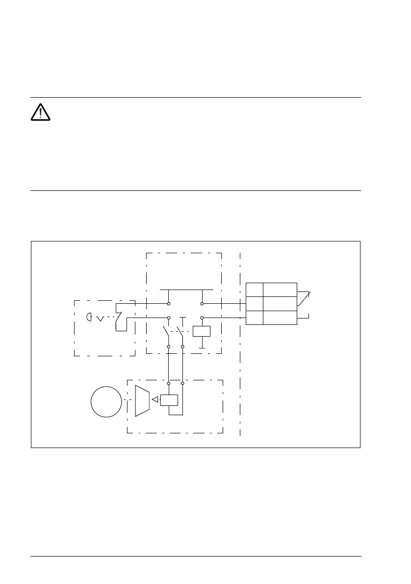
The figure below shows a brake control wiring example. The brake control hardware
and wiring is to be sourced and installed by the customer.
WARNING! Make sure that the machinery into which the drive with brake
control function is integrated fulfills the personnel safety regulations. Note that
the frequency converter (a Complete Drive Module or a Basic Drive Module, as
defined in IEC/EN 61800-2), is not considered as a safety device mentioned in the
European Machinery Directive and related harmonized standards. Thus, the
personnel safety of the complete machinery must not be based on a specific
frequency converter feature (such as the brake control function), but it has to be
implemented as defined in the application specific regulations.
The brake is controlled by bit 0 of parameter 44.01 Brake control status. In this
example, parameter 10.24 RO1 source is set to Brake command (ie. bit 0 of 44.01
Brake control status).
Motor
M
115/230 VAC
Mechanical brake
Brake control
hardware
Emergency
brake
5 NC
6 COM
7 NO
Drive control unit
ACS180 FW.book Page 84 Tuesday, March 9, 2021 2:25 PM

 Loading...


