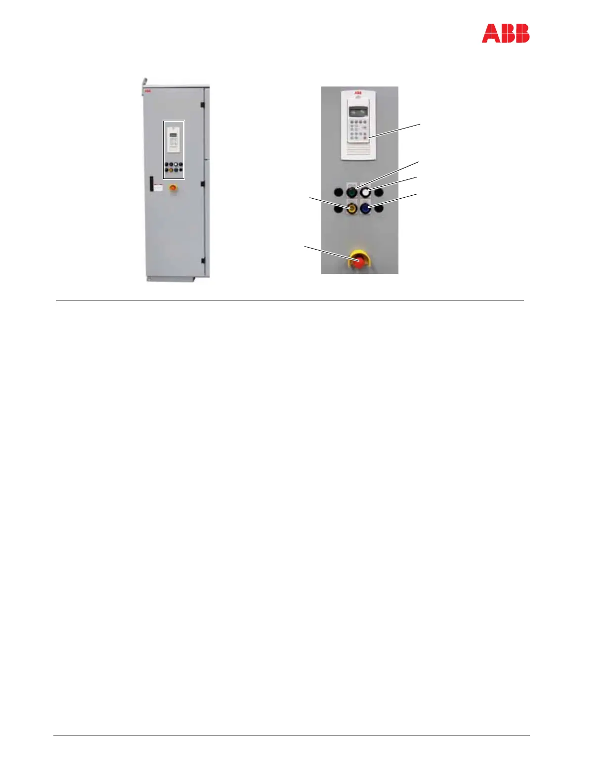
Legend
1 CDP control panel* - Starts and stops the motor
Displays status messages of AFE (Active Front
End) and INU (INverter Unit)
Displays alarm/fault messages of the drive and
monitored equipment
2 SUPPLY OFF
pushbutton
/ DISCHARGING
/ pilot light
green
light
Discharging - opens the MV switchgear and
initiates discharge of the DC link
Solid on: DC link discharged
Flashing: charging or discharging
3 SUPPLY ON
pushbutton
/CHARGING
/ pilot light
white
light
Charges the DC link and closes the MV switchgear
Flashing: charging or discharging
Solid on: DC link energized (MV switchgear
closed)
4 FAULT/ALARM
pilot light
blue
light
Flashing: alarm
Solid on: fault
5 GROUND SW RELEASED
pilot light
yellow
light
Solid on: indicates that the grounding switch can
be turned
6 Emergency OFF
pushbutton
- Removes power when pressed:
MV switchgear opens immediately and DC link
discharges
Motor coasts to a stop
* See Chapter 9 - CDP control panel for further information on the CDP control panel.
5
6
1
2
3
4
 Loading...


