Operation principle and hardware description
21
Operation principle and hardware description
What this chapter contains
This chapter describes the construction and operating principle of the drive in short.
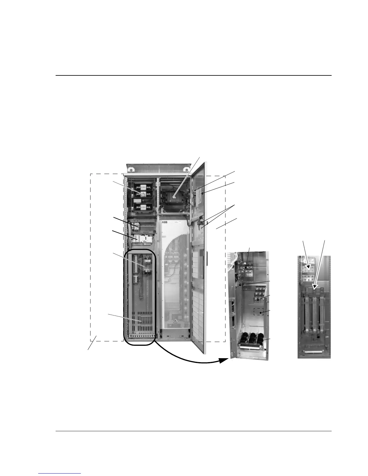
Product overview
The ACS800-07/U7 is a cabinet-installed drive for controlling AC motors.
Switch fuse (main
switch / disconnector)
Input
U1,V1,W1
Brake
resistor
(R-, R+)
*Emergency Stop and Start/Stop
switches
Output
U2,V2,W2
Cable
entries
PE
*du/dt filter (+E205)
behind the swing-out
frame
* Denotes optional equipment not present on
all units.
*Line contactor
Auxiliary circuit fuses
IP21/22 (UL type 1)
Power and signal cable terminals, and du/dt
filter (+E205), behind the swing-out frame
Note: The input terminals are located in the
EMC filter cubicle with +E202.
Swing-out frame
For layout of optional
equipment on the
swing-out frame, see
Electrical installation /
Layout drawing of
factory installed optional
equipment
View of frame size R8
Control panel
Switch fuse handle
*Brake resistor cubicle with +D151
Drive
module
Drive control unit
(RDCU, RMIO)
+E205
*EMC filter cubicle with +E202
Input Output

 Loading...
