Electrical installation
75
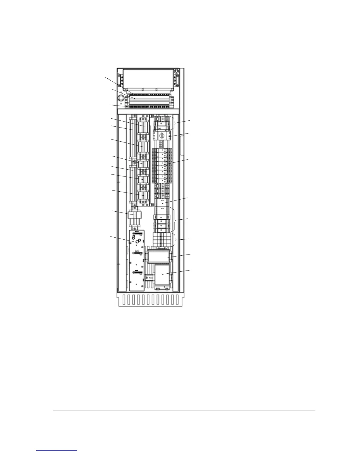
Frame size R7 and R8
For additional terminal blocks X1 to X10, see Additional terminal blocks.
Installation of brake resistors (units with brake chopper option)
See chapter Resistor braking. Connect the resistor as shown in section Power cable
connection diagram above.
*Thermistor/Pt100
relays
*Relay for Prevention of unexpected start-up
(option +Q950) or Safe torque off (option +968)
* Denotes optional equipment not present on
all units.
*AIMA board
*X2
*X1
+24 V external power
supply
* Motor auxiliary fan
devices
RDCU,
RMIO
Grounding clamps for
RMIO
Grounding clamps for
X2
*X5
*X7
*X8
*X9
*X4
*X10
*X6
*Earth fault protection device
*Emergency stop of
Category 1
Swing-out frame (front view)
64744291 A
*Circuit breakers for motor
and cabinet heaters
* Main contactor
control relays

 Loading...
