2 Installation and commissioning
2.3.6. Load diagram
3HAC026048-001 Revision: A54
© Copyright 2006-2008 ABB. All rights reserved.
2.3.6. Load diagram
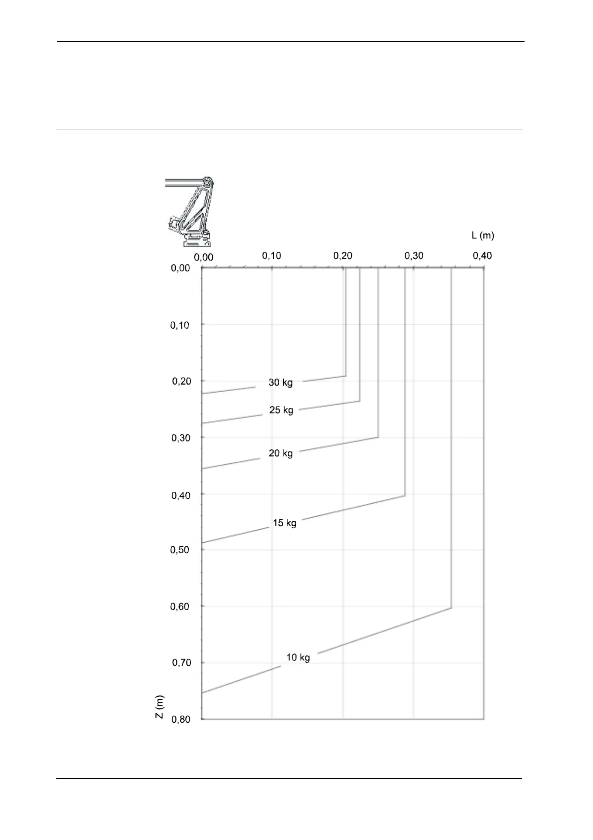
Load diagram, IRB 260-30/1.5
The figure below shows the maximum permitted load mounted on the robot tool flange at
different positions (center of gravity).
xx0500002100
 Loading...


