Installation and Commissioning On-Site Installation
Product Manual IRB 640 9
2.2 Assembling the robot
2.2.1 Manipulator
The three support points of the manipulator foot shall be mounted on three flat surfaces
with a flatness within the specification. Use shims if necessary. The rest of the surface
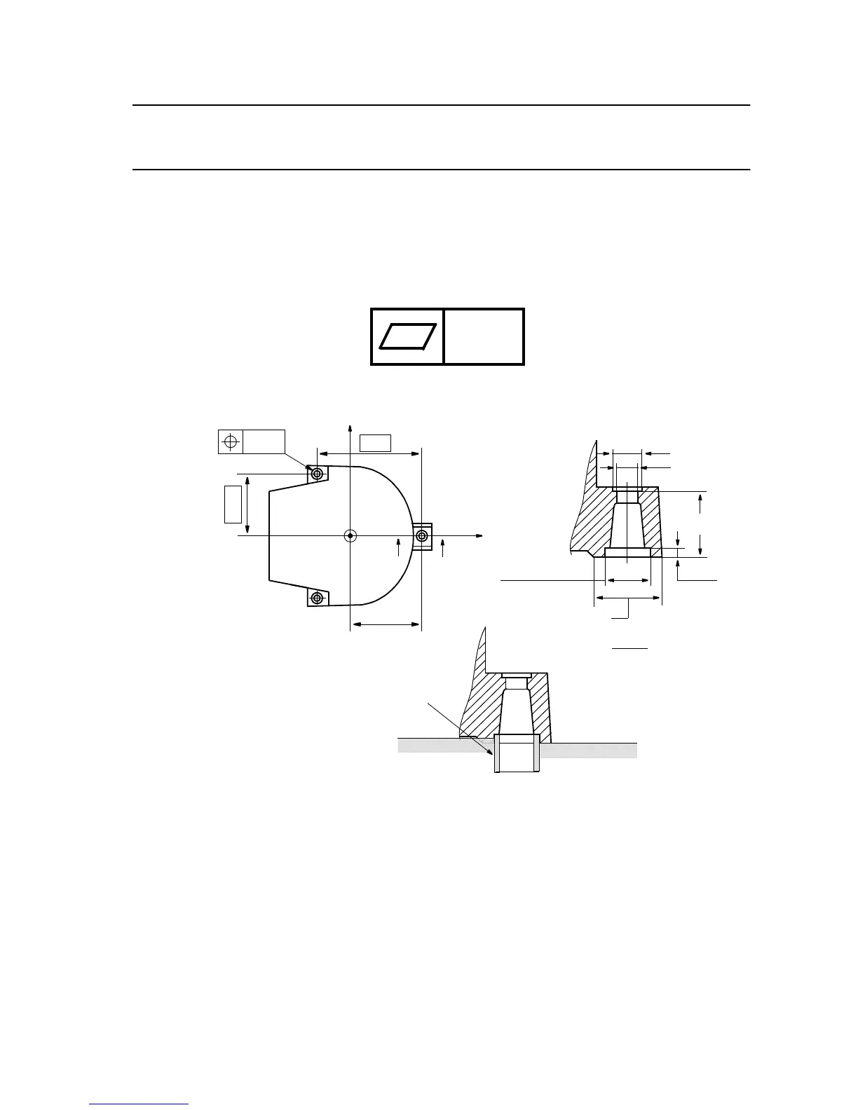
must be flat within ± 2 mm. Footprint diagram, see Figure 5. Floor mounted models
can be tilted max. 5
o
.
The levelness requirement for the surface is as follows:
Figure 5 Bolting down the manipulator (dimensions in mm).
The manipulator is fixed with three M30 bolts, tightened alternately.
Suitable bolts: M30x160 8.8 Socket screw with washer
Tightening torque: 1000 Nm
Two guide sleeves can be added to two of the bolt holes, to allow the same manipulator
to be re-mounted without program adjustment (see Figure 5).
When bolting a mounting plate or frame to a concrete floor, follow the general
instructions for expansion-shell bolts. The screw joint must be able to withstand the
stress loads defined in Chapter 2.3 Stress forces .
0.5
D=64 H9 (3x)
Support surface D=85 (3x)
A
0.2
720
480±0.1
A
∅
415.7
D=32(3x)
D=48(3x)
A - A
X
Y
Z
100 ±0,5
15
+2
0
Guide sleeve
 Loading...