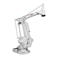
Axis 1 Repairs
12 Product Manual IRB 640
2.2 Cabling axis 1
Dismounting:
Refer to foldouts 2, 2:1 and 3.
1. Place axis 1 in calibration position 0. Shut down the robot system with the mains
switch.
2. Loosen the control cable connectors in the robot base.
3. Loosen the covers <2/21, 22> on base cabling from the base by unscrewing screws
<2/18>.
4. Loosen the support rail <3/3>, screws <3/6> and remove it forwards to a position
as far away from the base cabling as possible.
Do not remove the screws!
5. Loosen the base cabling at the bottom of the base <3/1>.
Do not remove the screws!
6. Tighten all screws <3/6> again after the cabling has been removed.
To avoid that the base plate <3/2> rotates and to make dismounting and mounting
of the cabling easier.
7. Take out the cover <2/22> and disconnect the earth wire from the contact plate in
the base.
8. Loosen the base cabling at the frame, screws <2:1/25>. The screws must be
removed.
9. Loosen the cover over axis 1 motor, the brake release unit and the serial measure-
ment board.
Caution!
The serial measurement board is an electrostatic sensitive device.
Use a wrist strap.
 Loading...