Axis 3 Repairs
30 Product Manual IRB 640
Mounting:
4. Lift the parallel bar in position.
5. Lubricate screws with Molycote 1000 and tighten to a torque of 300 Nm.
6. Make sure that the clamps are tightened symmetrically.
Do not forget to remove the 2 extra mechanical stops!
Tightening torque:
Screws, clamps, item 3.142: 300 Nm.
4.5 Dismounting upper arm, complete
Refer to foldout nos. 1 and 1:1.
Dismounting:
IMPORTANT! Secure axis 3 with two extra mechanical stops, so that the balanc-
ing weight for axis 3 cannot fall down.
1. Dismount balancing unit as described in Chapter 3.5, Dismounting balancing
unit or Chapter 3.6, Replacing guiding ring, balancing unit.
2. Remove the cables and air hose inside the lower arm as in Chapter 3.8, Dis-
mounting cables, lower arm/upper arm
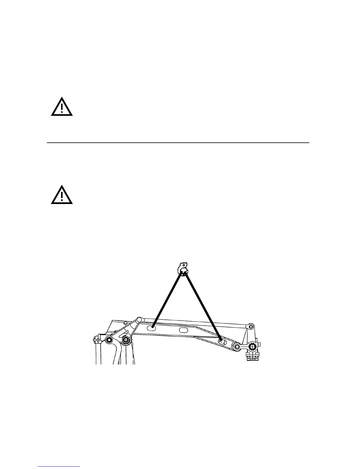
3. Attach a hoist to the upper arm. See Figure 6.
Figure 6 Lifting the upper arm.
4. Dismount the linkage as described in Chapter 5, Link system.
5. Unscrew the clamps, screws <1/3.143> on the upper arm for the parallel bar. Let
the bar rest on the weights. NOTE! Mark the clamps.
5. Remove the KM nut<1:1/136> on each shaft.
 Loading...