General Description Repairs
4 Product Manual IRB 640
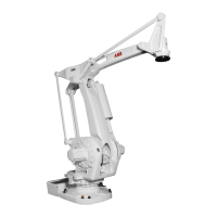
Axis No. 1 rotates the robot via a frame.
Axis No. 2, which provides the lower arm´s reciprocating movement, is supported in
the frame. The Lower Arm forms together with the Parallel Arm and the Parallel
Bracket, a parallelogram against the Upper Arm. The Parallel Bracket is mounted in
bearings in the Parallel Arm and in the Upper Arm.
Axis No. 3 provides elevation of the robot's upper arm.
Axis No. 6 is a turning motion. A connection is arranged for various customer tools at
the front end of the wrist in the Turn Disc. The tool (or manipulator) can be equipped
with pneumatic control via an external air supply. The signals to/from the tool can be
supplied via internal customer connections.
The Control Cabinet must be switched off during all service work on the robot!
Before doing any work on the robot measurement system (measurement board,
cabling), the accumulator power supply must always be disconnected.
When service work is finished, the calibration position should always be checked with
the system disc.
The Brake Release Unit should be connected as indicated in Section 7, Installation and
Commissioning, to enable movements of the axes.
Special care must be taken when the brakes are operated manually. This applies
particularly when the robot is started up, either for the first time or after a stop-
page. The safety instructions in the Programming Manual must be complied with
at all times.

 Loading...