127
Chapter 5 Theory of Operation
Front Panel
4
5
Front Panel
See “A2 Keyboard Schematic” on page 205 and “A2 Display Schematic”
on page 206.
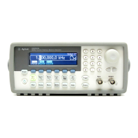
The front panel contains a keyboard, a liquid crystal display (LCD),
a piezoelectric speaker, and a rotary encoder.
The keyboard is arranged in five columns and eight rows. The keys are
scanned one column at a time. Some of the keys have an LED incorporated
into the key to indicate the instrument’s operating state. U301 scans the
columns and reads the key presses.
The rotary encoder uses a quadrature coding technique to allow the
motion, speed and direction to be detected. The two sense lines from the
rotary encoder are buffered by U215 and applied to two of the TPUCH
inputs of the main CPU. The main CPU tracks and accumulates knob
motion information.
The display is a 256 X 64 passive matrix color LCD. This display assembly
includes the backlight lamp and LCD driver circuitry. The display is
lighted by a replaceable, 3-watt, cold cathode fluorescent lamp. The lamp
is powered by an inverter module that is current-regulated to supply
4.8 mA at approximately 300 Vdc. The backlight inverter module can
be turned off by the LCD control circuitry.
U402 (on schematic 4) is the display controller. This controller reads the
main CPU data and address lines and stores appropriate display data in
SRAM U403. U403 runs continuously. U402 checks for main CPU
activity before turning on the display to prevent burn-out. The CPU
firmware incorporates a “bulb saver” feature that turns off the display
after 1 hour of inactivity. R410, R412, R413, R415, and R418 provide the
wake up configuration for the display controller.
The speaker is a piezoelectric element driven by U213-C from signals
generated in the main CPU U202. The frequency and duration of the
beeps are set by the main CPU.

 Loading...