89
Chapter 4 Calibration Procedures
Duty Cycle Adjustment
4
4
Duty Cycle Adjustment
The function generator stores a calibration constant used to calculate
the square wave duty cycle. This setup outputs a 25.1 MHz square wave.
The output frequency in this procedure is chosen to avoid artifacts of
DDS signal generation and internal clock frequencies.
The “Internal ADC Adjustment”, on page 75 must be completed before
doing this procedure.
1 Set the oscilloscope to 50Ω input termination (if your oscilloscope
does not have a 50Ω input termination, you must provide an external
termination). Make the connections shown on page 87.
2 Use an oscilloscope to measure the duty cycle of the signal at the front-
panel Output connector.
* Constants are stored after completing this setup.
3 Using the numeric keypad or knob, adjust the displayed duty cycle at
each setup to match the measured duty cycle. Select ENTER VALUE.
4 There are no specific operational verification tests for the
Duty Cycle Adjustment.
5 Secure the instrument against further adjustments as described
on page 43.
You have now completed the recommended adjustment procedures.
You should now verify the output specifications of the instrument using
the “Performance Verification Tests”, on page 55.
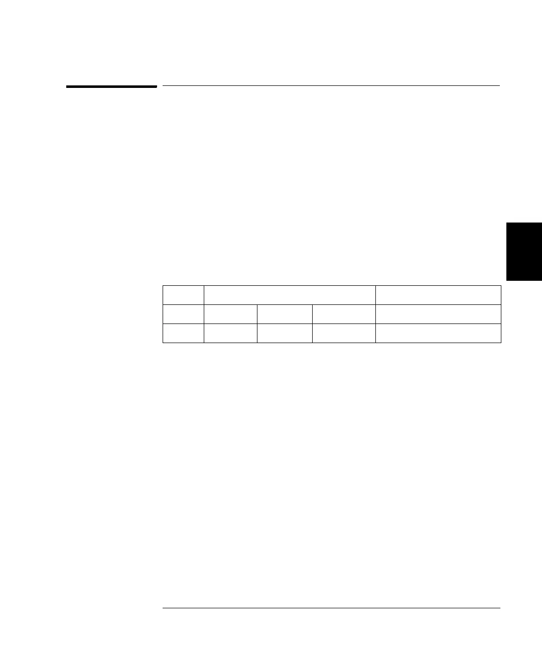
Nominal Signal
Setup Freq Amplitude Duty Cycle
115* 25.1 MHz 1 Vpp 50% Enter measured duty cycle

 Loading...


