87
Chapter 4 Calibration Procedures
Pulse Width (Trailing Edge Delay) Adjustment
4
4
Pulse Width (Trailing Edge Delay) Adjustment
The function generator stores calibration constants used to set the
trailing edge delay (see the discussion on page 110). These setups place
the instrument in pulse mode (at 8 MHz). Setup 102 must be performed
immediately prior to setup 103.
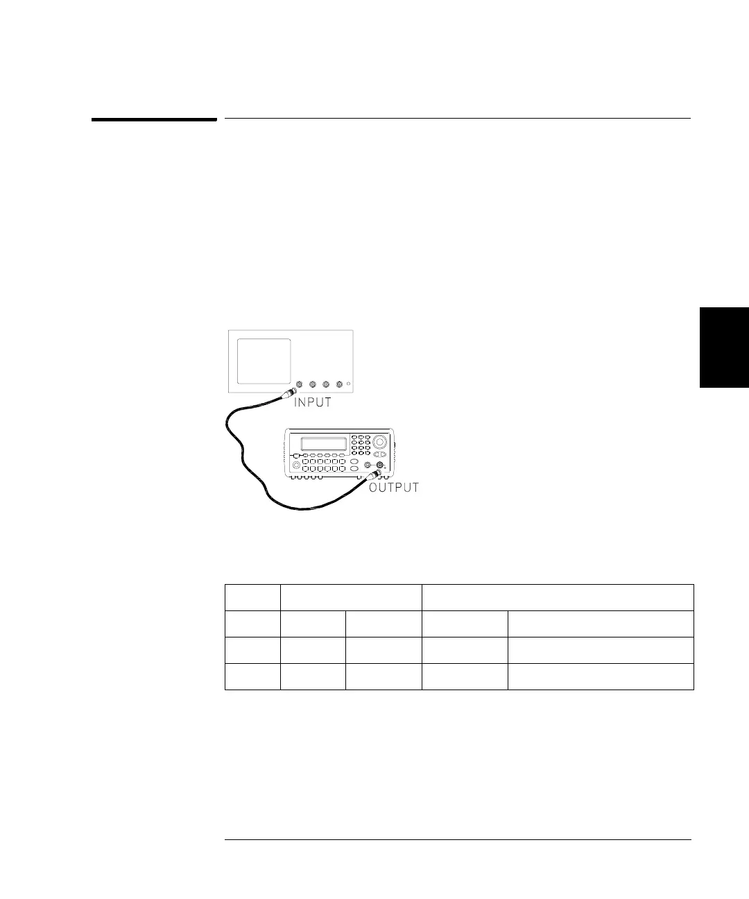
1 Set the oscilloscope to use averaging to determine the pulse width.
Set the oscilloscope to 50Ω input termination (if your oscilloscope
does not have a 50Ω input termination, you must provide an external
termination). Make the connections as shown below.
2 Use the oscilloscope to measure the pulse width of signal at the front-
panel Output terminal for each of the following setups.
* Constants are stored after completing this setup.
3 Using the numeric keypad or knob, adjust the displayed pulse width at
each setup to match the measured pulse width. Select ENTER VALUE.
4 There are no specific operational verification tests for the Pulse Width
Adjustment. Continue with the next adjustment procedure in this chapter.
Nominal Signal Measurement: Pulse Width(s)
Setup Freq Amplitude Pulse Width
102 8 MHz 1 Vpp 30 ns Narrow pulse width
103* 8 MHz 1 Vpp 42 ns Wide pulse width

 Loading...


